Biomedical Engineering Reference
In-Depth Information
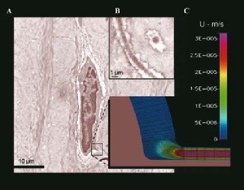
Figure 10.12.
Transmitted electron micrographs
of an osteocyte. Osteocyte (A) with inset showing
osteocyte process in the plane and perpendicular
to the plane of the micrograph, respectively; a
computational fluid dynamics model of a portion
of the osteocyte and its process predicts the fluid
velocity magnitudes within the pericellular space.
Reprinted from
,
Volume 33, E. J.Anderson, S. Kaliyamoorthy, J. I. D.
Alexander, and M. L. Knothe Tate, “Nano-microscale
models of periosteocytic flow show differences in
stresses imparted to cell body and processes,” p. 54
and cover image, 2005, with permission from
Springer.
Annals of Biomedical Engineering
10.9 Design Approaches:
The Tissue Engineer's
Computational Toolbox
Antonio Mikos. The scaffold is a prototype
developed with stereolithography and made of
poly(propylene fumarate) (PPF), a photopoly-
merizable, biodegradable resin. The scaffold is
a three-dimensional, layered cylinder with nine
circular and four semicircular channels in the
longitudinal direction (Fig.
A and B); all
channels are connected through seven trans-
verse rectangular channels. Scaffold geometries
are created using a solid modeling program
(Pro/Engineer, PTC) and then fabricated from
poly(propylene fumarate), PPF, with the aid of
a stereolithographic, rapid prototyping machine
(Viper si
10
.
13
The previous sections addressed variations in
length scale as they affect model building at the
level of the whole organ, the tissue, the cell, and
the molecule. Also discussed was whether to
approximate the system as a
continuum
or to
consider its structure
discrete
(Table
).
Although progress has been made in the fi eld
of tissue engineering, signifi cant challenges
remain in the regeneration and repair of bone,
a tissue that serves mostly structural and
mechanical functions. A major stumbling block
has been the lack of understanding of the mech-
anisms of transport to and between bone cells.
The importance of fl uid fl ow for the promotion
of cell viability and tissue health has been
described [
1
TM
,
2
3
D Systems, Valencia, CA). By
using
CT imaging methods (Scanco, Bassers-
dorf, Switzerland), actual geometries for the
prototypes (Fig.
µ
B) can be compared with
the target geometries. To predict fl ow through
the target design scaffold and through actual
rapid prototyped scaffolds, computational fl uid
dynamics methods were applied analogous to
those outlined in the previous section.
First, a fl uid mesh is created and fl uid fl ow is
calculated by using a CFD software package
(CFD-ACE, CFDRC, Huntsville, AL). In these
studies, we fi rst estimate the effects of noncon-
formance with specifi cations, i.e., the variance
between the target and the actual geometries, by
reducing iteratively (from
10
.
13
] in the earlier portions of this
chapter. The following case study illustrates one
example in which computational modeling can
be used to optimize engineered tissue design.
14
,
16
10.10 Case Study:
Design Optimization of a
Tissue-Engineering Scaffold
%
increments) the through-channel diameters in
the scaffold. Flow is induced by a pressure gradi-
ent for a fl uid medium idealized as water (density
=
1000
0
% to
100
% in
25
kg/m
3
, viscosity
kg/ms). On the
basis of the mass fl ow rate calculated through
the fl uid mesh of each computational scaffold,
permeability is determined by Darcy's law,
=
0
.
001
The case study has used a scaffold designed
by Dr. Lorna Gibson (MIT) and kindly provided
by Dr. David Dean, in collaboration with Dr.