Biomedical Engineering Reference
In-Depth Information
..
.
x t
( )
x t
( )
F
xt
()
x
..
.
F
y t
( )
y t
( )
y t
( )
()
y
M
C
K
..
.
zt
F
z
z t
( )
z t
( )
()
t
T
c
..
.
( )
( )
where: x, y - lateral, z - axial, θ - torsional deflection of the drill, matrices M,
C, K - mass, damping and stiffness characteristics at the drill tip, Fx, Fy lateral
forces, thrust Fz force, and Tc - torque.
It has been suggested that one of the ways to start the analysis of a process
as complex as drilling is to consider individual vibration mechanisms.
Therefore, Torsional-axial, lateral and whirling vibrations have been covered
individually in this paper [13].
2.1. Torsional-Axial Model
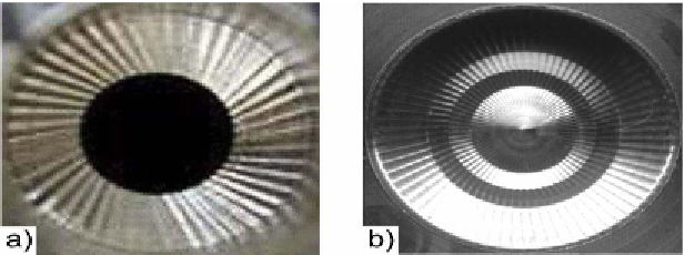
The coupling of torsional and axial vibrations happens when the drill
starts to lengthen and shorten respectively due to the torsional vibration
creating a wavy surface at the bottom of the hole (Figure 4). As the previous
material surface profile influences the next cut, a regenerative effect of thrust
and torque acts on the tool. This can lead to an increase in the vibrations of the
system, leading to unstable vibrations during machining. This is why it is
necessary to determine stability boundaries for the torsional-axial model.
(Source: UBC - M.A.L.),[13] .
Figure 4. (a) chatter surface on the bottom surface of a hole for a twist drill (with pilot
hole); (b) for an indexable drill.