Civil Engineering Reference
In-Depth Information
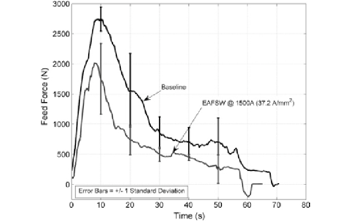
11.3.3.1 Comparison of Feed Force
Figure
11.32
shows the comparison of feed forces in conventional FSW and
EAFSW with respect to time. The curves are aligned such that the time zero on the
abscissa is when the feed was started and the error bars represent
±
one standard
deviation. From the figure, it can be concluded that the overall feed force in an
EAFSW process is less than that in a conventional FSW process. The decrease in
feed force on average is approximately 58 %.
The large increase in force at the start of the welding process indicates the
beginning of the tool feed. After the initial peak at the start of the feed, the magni-
tude of feed force decreases slowly until the feed is stopped.
In the conventional FSW process, the material is subjected to relatively cold
material flow at the start of the feed and the transportation of the material by the
tool involves high frictional force, as there is little thermal softening of the mate-
rial. Again, only a small dwell time was used before the feed was started. Due to the
limited amount of thermal softening, which creates high resistance to material flow,
a higher feed force is required at the start of the feed. As the weld progresses, heat
is generated from the friction between the tool and the workpiece and from material
deformation. The heat generated from the friction between the pin of the tool and
workpiece and due to material deformation is small compared to the heat generated
due to the friction between the shoulder of the tool and workpiece. Hence, the design
of the tool flange is critical in FSW processing. As the tool traverses the weld line,
the feed force decreases from the peak force and nearly reaches a steady-state force
as the heat transfer begins to equalize. This means that the heat generated is equal to
the heat loss from the system; thus, the temperature during the weld is stabilizing.