Biomedical Engineering Reference
In-Depth Information
Geometry of pelvis
Mean geometry
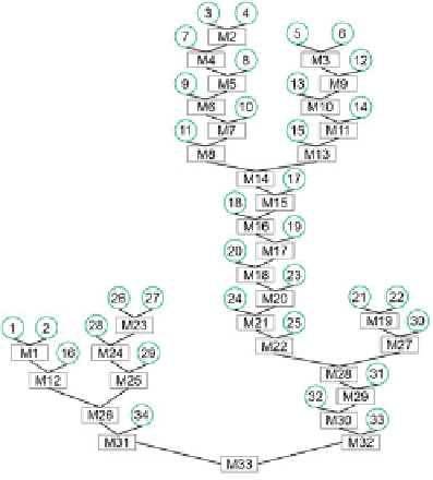
Fig. 7
Dendrogram after the clustering of 34 pelvis geometries
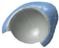
Fig. 8
Designed prosthesis
by means of the derived
universal geometry
universal geometry
cupaddendum
the mean geometries by the grey square. The numbering of the trimmed geometries
and the mean geometries is executed in the order of combination and generation.
It can be noted that a minimum of 2 clusters results, these with the universal
geometry
M
31 and with the geometry
M
32. For the design of a first universal hip
cup and a first forming die the geometry
M
32 was used. This selection results the
visual check of the dendrogram and from the fact that
M
32 represents the biggest
amount of geometries.
4.3.4 Standardized Hip Cup Prosthesis
In Fig.
8
the derived hip cup prosthesis is pictured. This prosthesis consists of the
deducted universal geometry of the trimmed pelvis (blue area) and an cup addendum
(grey area).
The cup addendum is designed by means of Catia V5 (Dessault, France). For
the design of those addendum a hemisphere with a diameter of 22mm is created,