Civil Engineering Reference
In-Depth Information
P
u
c
h
q
u
= P
u
/A
f
Figure 7-10 Plain Concrete Footing
To allow for unevenness of excavation and for some contamination of the concrete adjacent to the soil, an
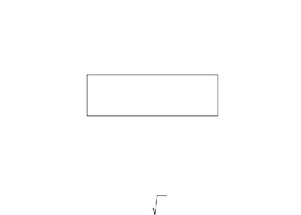
additional 2 in. in overall thickness is required for plain concrete footings; thus,
P
u
For
f
c
=
ʹ
3000 psi: h
=
4.5c
A
f
+
2in.
P
u
For
f
c
=
ʹ
4000 psi: h
=
4.15c
A
f
+
2in.
The above footing thickness equations are in mixed units:
P
u
= factored column load, kips
A
f
= base area of footing, sq ft
c = greatest distance from face of column to edge of footing, ft (ACI 318, Section 22.7.5)
h = overall thickness of footing, in. > 8 in. (ACI 318, Section 22.7.4)
Thickness of plain concrete footings will be controlled by flexural strength rather than shear strength for the
usual proportions of plain concrete footings. Shear rarely will control. For those cases where shear may cause
concern, the nominal shear strength is given in ACI 22.5.4.
7.8.1 Example: Plain Concrete Footing Design
For the interior columns of Building No.2, (Braced Frame), design a plain concrete footing.
From Example 7.7:
A
f
= 9 ft-10 in.
9 ft-10 in. = 96.7 sq ft
P
u
= 512 kips
c = footing projection = 4.25 ft


Search WWH ::

Custom Search