Graphics Programs Reference
In-Depth Information
4.
Hover your mouse over one of the reference lines, and notice that
it highlights to show a preview of the line that will be created. Click
each of the reference lines only once. A pink sketch line appears after
each click. When you're finished you should see an image similar to
Figure 1.6.
FIgUre 1.6
Floor sketch lines based on reference
planes
5.
Try clicking the green check mark in the ribbon to commit your sketch
lines. You will get an error about intersecting lines. Click Continue,
and you will resolve this error. Revit requires that sketches be closed
loops, and you have overlapping intersections at each of the corners.
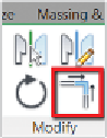
6.
Find the Trim/Extend To Corner tool in the Modify panel of the
Modify | Create Floor Boundary tab in the ribbon. Click the tool and
hover your mouse over a portion of one of the sketch lines that you
want to keep; it highlights blue. Then click the line. Next, click the
portion of the intersecting line that you wish to keep. Revit will trim
the unwanted segments from the corner.
▶
7.
After the first corner is cleaned up, Revit remains in the Trim/Extend
To Corner tool; click the next two intersecting lines to clean up their
corner. Repeat these steps until each corner is cleaned up, as in
Figure 1.7.
The status bar in the
lower-left corner of the
UI provides feedback
when using commands
like Trim. It also displays
keyboard shortcuts as
you type, and it reports
what object your mouse
is hovering over.
8.
Finally, click the green check mark; this time you should be
successful. Revit has the floor selected when you exit sketch mode.
You should see the blue selection color, and you can review your
floor's properties in the Properties palette. The floor is on Level 1,
and its Area is 2500 SF (762 m).


Search WWH ::

Custom Search