Graphics Programs Reference
In-Depth Information
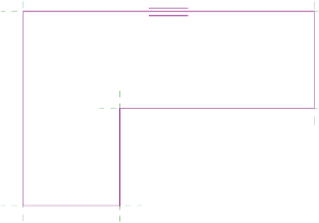
FIgUre 1.7
Floor sketch lines after trimming the corners
This concludes Exercise 1.5. You can compare your results with the sample
ile
c01-ex-01.5end.rvt
.
exercise 1.6: Create Walls
Open the file
c01-ex-01.6start.rvt
to start this exercise.
1.
Find the Wall tool in the Architecture tab of the ribbon. Click the
Wall tool and choose the Pick Lines tool from the Draw gallery.
2.
Turn your attention to the Properties palette. You will set a few
parameters
before
you draw your walls. Change the Location Line
parameter by clicking in the cell and choosing Finish Face: Exterior
from the drop-down list.
3.
Also in the Properties palette, change the Top Constraint parameter
to Up To Level: Level 2.
4.
Now hover your mouse over one of the edges of the floor. Do not click
your mouse yet. Notice the light-blue dotted line that appears. This
line indicates whether the wall will be placed inward or outward from
the reference line. Note that you may need to zoom in to see the blue
dotted line.
5.
You want your walls to be inward from the green reference line, so
move your mouse slightly inward from the floor edges — until the
blue dotted line is on the inside — then click your mouse. Repeat for
each edge until your drawing looks similar to Figure 1.8.


Search WWH ::

Custom Search