Environmental Engineering Reference
In-Depth Information
The region
m
>
1 is called overmodulation, and the output voltage is further in-
creasing in nonlinear way. The maximum is the case of square-wave modulation
according to (4.7), which occurs at a value of
m
dependent on the frequency ra-
tio
m
f
. The voltage waveform contains harmonics, with foremost order numbers
(
m
f
±
2)
,
(2
m
f
±
1) and (3
m
f
±
2), their amplitude values depending on the modu-
lation ratio
m
.
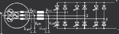
In a symmetrical three-phase circuit as shown in Fig. 4.9, the phase voltages also
form a symmetrical system; Fig. 4.10 indicates the waveform envelope for PWM
modulation. The load currents are determined by the load impedances.
4.3.3.3 Active Front-End Inverter
A self-commutated inverter combined with an a.c. side inductor, called active front-
end inverter, is often used to couple a three-phase a.c. system with a d.c. circuit such
as a voltage-source intermediate circuit. It is capable of conducting active power
and of reactive power in both directions, thus allowing control of the power factor.
Its operation is discussed using a.c. complex calculation for sinusoidal fundamental
quantities.
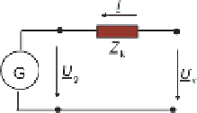
Figure 4.11 is the model, where compared with Fig. 4.9, instead of a grid there is
now an electrical machine on the load side which may be an induction generator. An
inductor of impedance
Z
k
couples the machine terminals with the a.c. side terminals
of the inverter,
U
g
and
U
v
are fundamental frequency per phase r.m.s. voltages of
the generator and the inverter, respectively. A voltage drop at impedance
Z
k
is due
to current
I
.
Using complex calculus, and fixing vector
U
g
along the real axis, the current can
be expressed by:
1
I
=
U
g
Z
k
e
j
β
−
λ
=
|
U
v
|
U
g
e
j
ϕ
k
where
U
g
=
U
g
;
λ
;
β
= arc(
U
v
)
,
Z
k
=
R
k
+
j
ω
1
L
k
=
Z
k
·
In Fig. 4.12 four example cases are illustrated, using the conventional consumer
(motor) coordinate system. In the upper row cases active power is supplied to the
machine (motor operation), while the lower row cases are for power supplied to
Fig. 4.11
Model of generator, coupling inductor and inverter
Search WWH ::

Custom Search