Environmental Engineering Reference
In-Depth Information
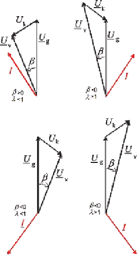
Fig. 4.12
Phasor diagram of
a.c. fundamentals in different
cases of operation
the converter intermediate circuit (generator operation). On the other hand the left
column cases denote reactive power supply from the machine side (over excitation,
capacitive), while the right column cases indicate reactive power consumption (un-
der excited, inductive).
The complex apparent power of the three-phase system becomes:
e
j
ϕ
k
1
where
S
re f
=
3
U
g
Z
k
e
−
j
β
−
S
= 3
U
g
I
∗
=
S
re f
·
λ
(4.10)
I
∗
denotes the conjugate complex of
I
, and
S
ref
is a reference apparent power.
Assumming a lossless inductor impedance,
Z
k
= j
ω
1
L
,
ϕ
k
=
π
/
2, the following
approximation is obtained:
S
=
3
U
g
e
−
j
β
−
β
−
·
ω
1
L
[
λ
sin
β
+ j(
λ
cos
1)]=
S
re f
j(
λ
1)
(4.11)
A further approximation may be given for small values of
β
; indicating a simple
concept to decoupled control of active power (by
β
) and reactive power (by
λ
).
S
≈
S
re f
[
λ
·
β
+ j(
λ
−
1)]
(4.12)
In Fig. 4.13 active and reactive power behaviour is shown depending on ratio
λ
for lossless inductor. Examples of operation in each of the four
quadrants are reflected by the phasor diagrams of Fig. 4.12. Note that an induction
and angle
β

Search WWH ::

Custom Search