Environmental Engineering Reference
In-Depth Information
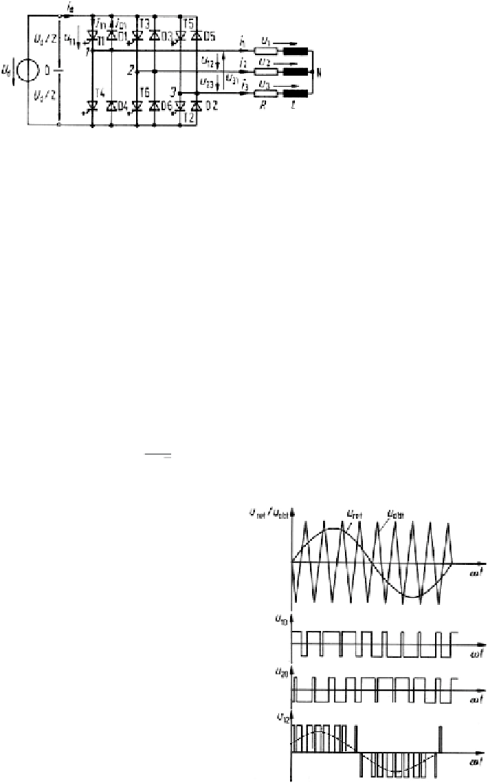
Fig. 4.9
PWM bridge (B6) inverter circuit
Many pulse pattern generation schemes are known, fulfilling different optimiza-
tion approaches. One of the most popular ones is the pulse width modulation
(PWM). A synchronous modulation using sinusoidal reference voltages
u
ref
and a
triangular carrier voltage
u
tri
is illustrated in Fig. 4.10. The frequency ratio of the
triangular and reference voltage which should be an uneven integer is
m
f
= 9inthe
example. Switch pairs connect an output branch either to the positive or negative d.c
terminals, depending on whether
u
ref
>
u
tri
or
u
ref
<
u
tri
. This is shown in the Figure
for
u
10
and
u
20
, resulting in the output line-to-line voltage
u
12
.
The modulation ratio is defined using reference and triangular voltage ampli-
tudes:
u
re f
u
tri
m
=
(4.8)
In the region
m
≤
1 the fundamental output line-to-line voltage is a linear function
of
m
:
U
12
=
√
3
2
√
2
m
·
U
d
= 0
,
612
·
m
·
U
d
for
m
≤
1
(4.9)
Fig. 4.10
Voltage waveforms
in PWM operation with
sinusoidal modulation
Search WWH ::

Custom Search