Civil Engineering Reference
In-Depth Information
Recrystallized grain structure
Columnar grains
Cutout to show structure
Fine-grained,
nanocrystalline,
with preferred
orientation
Zone 3
Zone 2
T
*
Zone T
1
Zone 1
t
*
0.5
Region not
accessible
0.2
0.1
Porous,
tapered crystallites
separated by voids,
tensile stress
10
-1
Ion etching
zone
1
Densely packed
ibrous grains
10
Transition from tensile (low
E
*) to
compressive stress (high
E
*)
10
2
Line separating
net deposition
and net etching
Region not
accessible
10
3
E
*
Region of possible
low-temperature
low-energy ion-assisted
epitaxial growth
Region of max.
compressive stress Reduction of deposition
by sputtering, dense ilm,
amorphous for some materials
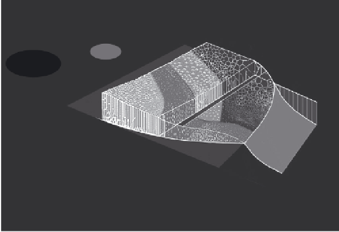
8.3
Schematic diagram showing nanostructures of thin fi lms made by
sputter deposition as a function of generalized temperature
T
* and
energy fl ux
E
*, and with
t
* denoting fi lm thickness. Ion etching can
take place at high energy fl ux. From Anders (2010).
A fi lm that is thicker than those in Fig. 8.1 develops a characteristic
nanostructure also over its cross section. Figure 8.3 is a recent extension
(Anders, 2010) of a well-known structure zone diagram, known as a
'Thornton diagram' (Thornton, 1977), and illustrates what happens. The
fi gure applies to sputtering and shows that the fi lm typically exhibits a
columnar structure oriented perpendicular to the substrate, and that this
structure depends critically on the deposition parameters, especially on the
energy of the sputtered species (in its turn related to the pressure in the
sputter plasma, typically comprised of argon) and the substrate tempera-
ture. The structure of an evaporated fi lm is found in the limit of a small
argon pressure; it was described already in the 1960s (Movchan and Dem-
chishin, 1969) and the modelling was subsequently refi ned (Barna and
Adamik, 1998; Hultman and Sundgren, 2001).
For many thin fi lm applications, there is a requirement for high durability,
which means that compact fi lms are wanted, and historically the sputter-
based technology was developed to prepare fi lms that were more durable
than those made by evaporation. Parameters leading to fi lms belonging to
'zone T' in the 'Thornton diagram' are then preferred. For other applica-
tions, however, it is desirable to make fi lms with a carefully chosen


Search WWH ::

Custom Search