2.7
CELP coders are in essence linear predictive coders equipped with an ABS search procedure. They were invented in the 1980s by Bell Labs (under the supervision of B.S. Atal and M.R. Schroeder). As we have already seen, once the short-term correlation in the signal has been removed by the LPC filter and the long-term correlation (or pitch contribution) has been removed by the LTP filter, the quality of reproduction depends essentially on the selection of an optimal excitation signal.
A possible choice is a multi-pulse excitation signal. The position and amplitude of each pulse are searched iteratively using an ABS algorithm. The main pulse position is searched first, then the algorithm locates the optimal second pulse, and so on. The coder bitstream must encode the position and amplitude of each pulse modeling the excitation. Note that the regular pulse solution used in the GSM full rate is a particular case of the multi-pulse excitation signal, which significantly decreases the computing power required for computation of a general multi-pulse excitation signal.
The optimization of a multi-pulse signal is very complex in general, because the number of candidate vectors is very large. In CELP coders, a codetopic based on vector quantization is built, trained, and optimized off-line on a large ‘speech’ database. Only these vectors are used as candidates for the excitation generator that feeds the LTP and LPC synthesis filters. The excitation signal (index in the codetopic and value of gain) that best approximates the original speech input signal is selected according to a perceptual error criterion.
The role of the perceptual filter is to redistribute noise in frequency ranges where it will be less audible due to the higher energy of the main signal: the noise will be masked by the signal itself. Significant improvements of the subjective quality [A3] are observed when using this perceptual weighting filter. The filter W(z) = A(z)/A(z/y), with a bandwidth expansion coefficient y less than 1, forces the noise to be reinforced in the neighborhood of the formants and to be lowered in the region where the signal is weak. Although absolute noise power is generally increased, listeners generally prefer this situation.
One big issue with CELP coders is the difficulty of finding the best index and associated gain in the codetopic, as the codetopic is very large. For a long time, this has been a barrier to practical implementation in real time. Algorithmic simplifications brought to the initial design (efficient codetopic search or algebraic codetopics) and the growth
of available MIPS (million instructions per second) in modern DSPs have finally made it possible to implement CELP coders in real time.
The basic scheme of a CELP coder is shown on Figure 2.51.
LPCs are first computed and quantized for an entire frame of speech (10-30 ms). Vector quantization and line spectrum pairs are increasingly used due to their efficiency. LTP lag and gain are searched and quantized on a subframe basis as well as the codetopic index and associated gain Gi.
The decoder is much less complex than the encoder (there is no ABS search procedure) and can include an optional post-filter as shown in Figure 2.52.
In order to improve perceived quality, the post-filter aims at reducing the noise level in frequency bands located between the maxima of the spectrum (located near the harmonics). A typical implementation is a short-term post-filter which is derived from LPCs in a similar way as the perceptual weighting filter in the encoder. Modern post-filters can also include a long-term prediction post-filter and a tilt compensation post-filter. The introduction of the post-filter can significantly increase the MOS rating of CELP decoders; nevertheless, it may affect the fidelity of decoded speech if its action is exaggerated.
The basic scheme for a CELP encoder relies on an open-loop search for the long-term correlation coefficients of the LTP filter. A more advanced implementation refines this procedure by first conducting an open-loop search for an LTP lag, then testing fractional lags in the neighborhood of this initial lag in an adaptive codetopic. The chosen value is selected by an ABS-MSE (mean square error) procedure.
The remaining components (called innovations) of the residual signal are nonpre-dictable, and a best matching excitation vector is searched in another codetopic, called the stochastic codetopic. The design of the stochastic codetopic, which models samples that more or less resemble noise, is complex. There are two main approaches. The first
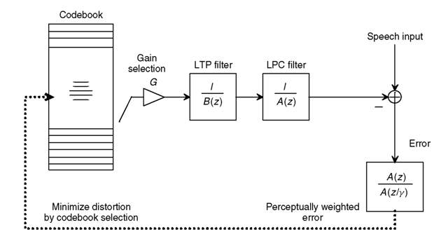
Figure 2.51 Basic concept of a CELP coding algorithm. The quantized LTP and LPC parameters are transmitted on a frame basis. The quantized gain G and the codetopic index are transmitted (sometimes on a subframe basis).
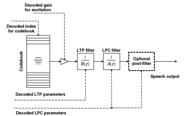
Figure 2.52 Basic concept of a CELP decoding algorithm.
is to build the codetopic before the execution phase of the encoder by using training and optimization on large speech databases. The second is based on a predetermined set of patterns, which are combined, resulting in the optimal excitation vector (see Section 2.7.1 on G.729 for an example). The optimal combination is computed during the ABS mean square error procedure (e.g., selection of the pulse location and associated gain). The latter method is used, for example, in ACELP (algebraic CELP) or MP-MLQ (multipulse maximum likelihood quantization).
The algorithm is therefore based on a closed-loop search in two codetopics:
• The adaptive codetopic which is devoted to long-term prediction.
• The stochastic codetopic which deals with those components in the residual signal that are nonpredictable.
The closed-loop search selects four parameters:
(1) An index in the stochastic codetopic.
(2) An optimal gain corresponding to the index selected in the stochastic codetopic.
(3) A lag (integer or fractional) in the adaptive codetopic.
(4) An optimal gain corresponding to the selected lag value.
The optimal excitation search for the LPC synthesis filter is therefore modified as shown in Figure 2.53.
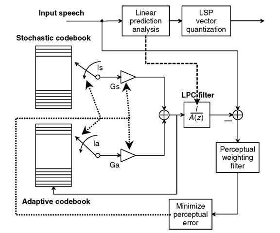
Figure 2.53 Advanced concept of a CELP encoding algorithm. Is, Gs, Ia, Ga, and the LPC (LSP) parameters are transmitted.
Using such algorithms (ABS with stochastic and adaptive codetopics, and LSP vector quantization), CELP speech coders excel in the range 4.8-16 kbit/s. Many international standards in that range of bitrates are CELP or derivative CELP speech coders:
• Federal Standard 1016 4800 bit/s CELP [A17].
• ITU-T 8-kbit/s G.729 CS-ACELP and dual-rate multimedia ITU-T G.723.1 (5.3 kbit/s and 6.3 kbit/s, ACELP, MP-MLQ).
• ITU-T low-delay CELP ITU-T 16-kbit/s G.728. In order to fulfill the stringent requirement of low delay, a long LPC backward-adaptive filter is used in place of the LPC and LTP classical filters; no LPCs are transmitted to the decoder side and only the index vector and associated gain is transmitted.
• ETSI enhanced full-rate GSM speech coder and the half-rate GSM speech coder, as well as the AMR and WB-AMR coders.
2.7.1
ITU-T 8-kbit/s CS-ACELP G.729
The ITU-T G.729 [A18] (Conjugate Structure Algebraic CELP) was proposed by the University of Sherbrooke, France Telecom, NTT, and ATT. It has a frame length of 10 ms with two subframes of 5 ms. The short-term analysis and synthesis are based on
tenth-order linear prediction filters. Due to the short frame length of 10 ms, LSPs (line spectral pairs) are quantized by using a fourth-order moving average (MA) prediction. The residue of linear prediction is quantized by an efficient two-stage vector quantization procedure (the CS used in the coder name refers to this). An open-loop search for the lag of the LTP analysis is made to select the initialization value for the closed-loop search in each subframe. Pitch predictor gain is close to unity, but the fixed codetopic gain varies much more. This gain is estimated by a fourth-order MA gain predictor with fixed coefficients, from the sequence of previous, fixed codetopic excitation vectors. This is the main difference between the G.729 encoder scheme and the one described on Figure 2.53; this gain predictor appears in the decoder scheme in Figure 2.54.
The lag and gain of the LTP filter, the optimal algebraic codetopic and the fixed algebraic excitations are jointly vector-quantized using 7 bits.
The innovation codetopic is built by combining four pulses of amplitudes +1or —1. The locations of the four pulses are picked from a predetermined set as shown in Table 2.9.
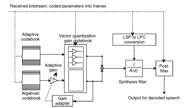
Figure 2.54 Basic principle of the ITU-T G.729 CS-ACELP 8-kbit/s speech decoder.
Table 2.9 Predetermined set of pulses of the innovation codetopic used by G.729
| Amplitude | Positions of pulses |
| ±1 | 0, 5, 10, 15, 20, 25, 30, 35 |
| ±1 | 1, 6, 11, 21, 26, 31, 36 |
| ±1 | 2, 7, 12, 17, 22, 27, 32, 37 |
| ±1 | 3, 8, 13, 18, 23, 28, 33, 38 |
| 4, 9, 14, 19, 24, 29, 34, 39 |
Table 2.10 G.729 bit allocation
| Parameter | Subframe of 40 samples | Frame of 80 samples | |
| 1st | 2nd | ||
| LSP | — | — | 18 |
| Pitch delay | 8 | 5 | 13 |
| Pitch parity | 1 | — | 1 |
| Algebraic code | 13 + 4 | 13 + 4 | 34 |
| Gain codetopic | 4 + 3 | 4 + 3 | 14 |
| Total | — | — | 80 |
The pulse positions of the first three pulses are encoded with 3 bits (eight possibilities) and the position of the fourth pulse is encoded with 4 bits (16 possibilities). Each pulse also requires 1 bit to encode the amplitude (±1). This gives a total of 17 bits for the algebraic codetopic in each subframe. Since only four nonzero pulses are in the innovation vector, very fast search procedures are made possible. Four nested loops corresponding to each pulse are used.
The structure of the final bitstream at 8 kbit/s is given in Table 2.10.
The G.729 decoder includes a post-filter consisting of three filters: a long-term post-filter, a short-term post-filter and a tilt compensation post-filter. The structure of the G.729 decoder is shown in Figure 2.54.
The ITU-T G.729 includes a detailed description in both fixed and floating point (annex C) with associated digital test vectors. Annex B describes a VAD/DTX/CNG scheme similar to G.723.1 (which was designed before G.729).
G.729 is recommended for use in voice over frame relay systems under the name clear voice. G.729 uses 16 MIPS. G.729 annex A is a lower complexity version (10 MIPS for the encoder compared with 18 MIPS) which was initially designed and recommended for DSVD (digital simultaneous voice and data systems), but is now widely used in VoIP systems. G.729 also defines extensions at 6.4 kbit/s (annex D) and 11.8 kbit/s (annex E) which target DCME and PCME applications.
2.7.2
ITU-T G.723.1: dual-rate speech coder for multimedia communications transmitting at 5.3 kbit/s and 6.3 kbit/s
2.7.2.1
Speech encoding
G.723.1 is the result of an ITU competition for an efficient speech-coding scheme at a low bitrate for videoconferencing applications using a 28.8-kbit/s or 33.4-kbit/s V.34 voice band modem; this resulted in a compromise between the two best candidates (Audiocodes and DSP Group on one side and France Telecom on the other). This explains the two models of innovation codetopics found in the standard: the MP-MLQ (Audiocodes) for the higher bitrate and the ACELP (University of Sherbrooke) for the lower bitrate. There are some subtle differences between the general, advanced, CELP speech-coding scheme presented previously and the G.723.1 general structure, but the
basic principles and algorithmic tools are the same. The excitation signal for the high-rate coder is multi-pulse maximum likelihood quantization (MP-MLQ) and for the low-rate coder at is algebraic code-excited linear prediction (ACELP, the principle used in G.729 and GSM EFR).
The frame size is 30 ms and there is an additional look-ahead of 7.5 ms, resulting in a total algorithmic delay of 37.5 ms. Subframe duration is 7.5 ms. The MP-MLQ block vector quantization resembles the algebraic vector quantization procedure: six pulses with sign ±1 for even subframes and five pulses with sign ±1 for odd subframes are searched with an ABS MSE procedure. There is also a restriction on pulse positions: the positions can either be all odd or all even (indicated by a ‘grid bit’). For the lower bitrate, the ACELP codetopic was tuned to fit 5.3 kbit/s.
Tables 2.11 and 2.12 give the bit allocation for the two bitrates. The 189 bits of the higher bitrate are packed in 24 bytes and the 158 bits of the lower bitrate are packed in 20 bytes. Depending on the selected rate, either 24 or 20 bytes must be sent every 30 ms. Two bits in the first byte are used for signaling the bitrate and for the VAD/DTX/CNG operations described in Section 2.7.2.2.
The ITU-T recommendation includes a 16-bit, fixed point, detailed description and a floating point reference program (annex B). Both are provided as ANSI C programs. For the floating point version, software tools were designed to allow implementers to check their realizations. Conformance to the standard can be checked by undertaking all the digital test sequences. The complexity in fixed point for the encoder and both bitrates is around 16 MIPS. Annex C, devoted to mobile application, includes some mobile channel error-coding schemes.
G.723.1 is—together with G.729—one of the most well known coders used in VoIP networks and is predominantly used in PC-based systems. While most embedded systems (such as network gateways) support both G.729 and G.723.1, some of the leading IP phone vendors unfortunately recently decided to stop supporting G.723.1. This situation makes the lives of network administrators difficult, since many PC to IP phone calls can only negotiate G.711 as the common coder.
Table 2.11 Bit allocation table for the 6.3-kbit/s G.723.1 encoder (MP-MLQ)
| Parameters coded | Subframe 0 | Subframe 1 | Subframe 2 | Subframe 3 | Total |
| LPC indices | 24 | ||||
| Adaptive | 7 | 2 | 7 | 2 | 18 |
| codetopic lags | |||||
| All the gains | 12 | 12 | 12 | 12 | 48 |
| combined | |||||
| Pulse positions | 20 | 18 | 20 | 18 | 73(Note) |
| Pulsesigns | 6 | 5 | 6 | 5 | 22 |
| Grid index | 11114 | ||||
| Total: | 189 | ||||
Note: By using the fact that the number of code words in the fixed codetopic is not a power of 2, three additional bits are saved by combining the four MSBs of each pulse position index into a single 13-bit word.
Table 2.12 Bit allocation table for the 5.3-kbit/s G.723.1 (ACELP)
| Parameters coded | Subframe 0 | Subframe 1 | Subframe 2 | Subframe 3 | Total |
| LPC indices | 24 | ||||
| Adaptive | 7 | 2 | 7 | 2 | 18 |
| codetopic lags | |||||
| All the gains | 12 | 12 | 12 | 12 | 48 |
| combined | |||||
| Pulse positions | 12 | 12 | 12 | 12 | 48 |
| Pulse signs | 4 | 4 | 4 | 4 | 16 |
| Grid index | 1 | 1 | 1 | 1 | 4 |
| Total: | 158 |
2.7.2.2
Discontinuous transmission and comfort noise generation (annex A)
In order to reduce the transmitted bitrate during silent periods in-between speech, silence compression schemes have to be designed. They are typically based on the voice activity detection (VAD) algorithm and a comfort noise generator (CNG) that reproduces an artificial noise at the decoder side. The VAD must precisely detect the presence of speech and send this information to the decoder side. The G.723.1 VAD operates on a speech frame of 30 ms, and includes some spectral and energy computations.
One interesting feature of the VAD/DTX/CNG scheme of the G.723.1 coding scheme is that, when the characteristics of environmental noise do not change, nothing at all is transmitted. When needed, only the spectral shape and the energy of the comfort noise to be reproduced at the decoder side are sent. The spectral shape of the noise is encoded by LSP coefficients quantized with 24 bits and its energy with 6 bits. With the two mode-signaling bits, this fits in 4 bytes. The two signaling bits in each packet of 24, 20, or 4 bytes indicates either a 24-byte 6.3-kbit/s speech frame, a 20-byte 5.3-kbit/s speech frame, or a 4-byte CNG frame. The G.723.1 can switch from one bitrate to the other on a frame-by-frame basis (each 30 ms). At the decoder side, four situations can appear:
(1) Receiving a 6.3-kbit/s frame (24 bytes).
(2) Receiving a 5.3-kbit/s frame (20 bytes).
(3) Receiving a CNG frame (4 bytes).
(4) Receiving nothing at all (untransmitted frame).
In situations (1) to (3), the decoder reproduces the speech frame or generates the comfort noise signal with parameters indicated in the CNG frame. In situation (4), the decoder incorporates some special procedures to reproduce a comfort noise based on previously received CNG parameters. Similar VAD/DTX/CNG schemes have been included in G.729 and its annexes.
2.7.3
The low-delay CELP coding scheme: ITU-T G.728
In general, CELP coders cannot be used when there is a requirement for a low-encoding algorithmic delay. This is due to the LPC modeling principle, which requires a frame length of 10-30 ms (average stationary period of the speech signal) to compute the LPC.
Traditional low-delay encoders, such as PCM and ADPCM waveform speech coders, introduce a very low delay and do not significantly impact network planning (introduction of electrical echo cancellers). Unfortunately, they do not work at low bitrates.
The ITU was looking for a relatively low-bitrate encoder (16 kbit/s), with a low algorithmic delay (maximum 5 ms).
The G.728 low-delay coding scheme was designed by AT&T [A20], which efficiently merged the two concepts of stochastic codetopic excitation (CELP) and backward prediction. In that scheme, there is no need to transmit the LPCs’ which are computed in both the encoder and decoder, in a backward loop. Since backward prediction works on the current frame of samples from data of the previous samples, a relatively long set of samples can be analyzed to optimize the LPC filter without requiring a long frame to be accumulated before transmission.
The synthesis filter used in the ABS-MSE loop procedure does not include any LTP filter, but, in order to correctly represent high pitch values (and to efficiently encode generic signals such as music), its length is extended to 50 backward coefficients, updated every 20 samples. The coefficients are not transmitted but adapted (computed) in a backward manner by using the reconstructed signal in the encoder and decoder.
The frame length for the innovative codetopics is equal to only 5 samples (0.625 ms). For each set of 5 samples, an index found in the stochastic codetopic of 128 entries is transmitted with a sign bit and a gain coded on 2 bits. In order to obtain an optimized codetopic structure (the vectors), a very long and time-consuming training sequence on a large speech signal database was necessary. The gain is not directly encoded on 2 bits: a linear predictor is used to predict the gain, and the error of the optimal gain versus the predicted gain is encoded and transmitted. This leads to Table 2.13, the bit allocation table for the LD-CELP G.728. The LD-CELP speech encoder principle is shown on Figure 2.55.
In order to increase resistance to transmission errors, the index of the codetopics is transmitted using Gray encoding. Unlike a normal binary system, Gray encoding ensures that adjacent integers only have a single bit of difference: while a bit error can result in a large error on the integer value, a bit error in Gray encoding minimizes the error in the
Table 2.13 G.728 bit allocation
| Bit allocation per frame | Bitrate (bit/s) | |
| Parameters | Numbers of bits | |
| Excitation Index | 7 | 11,200 |
| Gain | 2 | 3,200 |
| Sign | 1 | 1,600 |
| Frame length: 0.625 ms | (5 samples) | 16,000 |
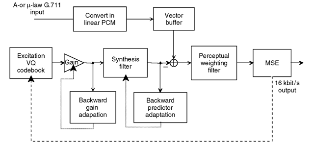
Figure 2.55 Low-delay CELP ITU-T G.728 encoder principle.
encoded value. For instance, integers 0 to 15 are encoded as 00, 01, 11, 10, 110, 111,
101, 100, 1100, 1101, 1111, 1110, 1010, 1011, 1001, 1000.
The introduction of the post-filter in the decoder shown in Figure 2.56 significantly improves the quality of decoded speech (this has allowed the AT&T proposal to fulfill the ITU-T requirements). G.728 has a very good score on the MOS scale (around 4) and is used in the H.320 videoconference system to replace the G.711 64 kbit/s with an identical quality bitstream of 16 kbit/s, leaving almost 48 kbit/s for the video on a single ISDN B channel. G.728 is also used in some modern DCME (digital circuit multiplication equipment), with extensions to 9.6 kbit/s and 12.8 kbit/s (replacing G.726 at 16 kbit/s,
24 kbit/s, and 32 kbit/s).
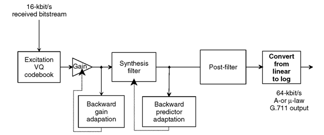
Figure 2.56 Low-delay CELP ITU-T G.728 decoder principle.
The major weaknesses of the original LD-CELP coding scheme are the difficulty to handle voice-band modem signals (an extension to 40 kbit/s is defined in annex I to solve this problem) and the high sensitivity to frame erasure due to the very long backward LPC filter and the use of a gain adaptation predictor. Recent work has significantly improved robustness and led to a new annex in the ITU-T G.728 suite of recommendations.
Another issue that G.728 shares with the G.729 coder (as opposed to the G.723.1 coder) is that there is no framing information in the transmitted bitstream. G.723.1 uses 2 bits in the first transmitted byte to indicate the type of packet. G.728 produces a 10bit code for each 5-sample frame, but the decoder must precisely know which is the first, second, third, and fourth packet of 10 bits in order to synchronize the backward LPC filter adaptation procedure (although speech remains intelligible with G.728 even if desynchronization occurs). Strictly speaking, the use of G.728 requires a delay of 4 frames (4* 0.625 ms = 2.5 ms).
In the H.320 suite of recommendations, the H.221 framing procedure specifies a positioning mechanism for four packets of 10 bits of G.728 (2 bits per byte of a 64-kbit/s stream) or 80 bits of the G.729 8-kbit/s stream (1 bit per byte of a 64-kbit/s stream).
The first detailed description introduced in 1992 was for a floating point DSP and two additional years of work were needed to finalize a fixed point (16-bit) description in annex G. Unfortunately, the description is not in the form of ANSI C code, but extensive documentation.
The complexity of G.728 in fixed point is around 20 MIPS for the encoder and 13 MIPS for the decoder.
2.7.4
The AMR and AMR-WB coders
The adaptive multi-rate (AMR) coder is the result of ongoing work by ETSI (European Telecommunications Standards Institute) and 3GPP (3rd Generation Partnership Project, founded in December 1998), in collaboration with T1 in the US, TTC (Telecommunication Technologies Committee) and ARIB (Association of Radio Industries and Businesses) in Japan, TTA (Telecommunication Technologies Association) in Korea, and CWTS (China Wireless Telecommunication Standard group) in China, for the third generation of cellular telephony systems. In the current generation of cellular systems, three voice coders are used:
• GSM-FR, standardized in 1987, produces a 13-kbit/s bitstream and provides relatively good quality, with good immunity to background noise.
• GSM-HR, standardized in 1994, reduces the bitrate to 5.6 kbit/s, but is much more sensitive to background noise, which prevented any significant deployment.
• GSM-EFR, standardized in 1996, enhances the voice quality of GSM-FR in the presence of background noise with a similar bitrate (12.2 kbit/s), but the enhancement is perceptible only on error-free transmission channels.
While most voice coders seek to optimize the bitrate for a given quality of transmission channel for a desired voice quality level, so far little work has been done to take into
account the variable quality of a transmission channel. On most wire lines, it is true that the quality of transmission lines does not vary significantly, but obviously this is not the case for wireless transmission channels. With VoIP, the network conditions experienced by a PC-based phone, for instance, may also vary widely depending on whether the connection is via Ethernet, WiFi, at the office, or at a hotel. When the quality of the transmission channel varies, the optimal allocation of bits between source encoding and channel encoding varies: as the quality of the transmission link decreases, it becomes more efficient to allocate more bits to error protection schemes and fewer bits to the source encoding algorithm. Instead of optimizing the next generation coder for a given bitrate or transmission quality, it was decided that the new coder should be able to adapt to variable conditions (a ‘multi-rate’ coder) and provide optimal behavior under all these conditions (‘adaptive’). The goals were:
• To improve the quality of GSM-FR on a channel with transmission errors, for a similar bitrate.
• To provide acceptable quality even on half-rate transmissions, in order to enhance transmission density in case of congestion.
• To adapt dynamically to the conditions of the radio channel.
The narrow-band AMR coder was standardized in March 1999; in addition, it was decided to study a version of the AMR coder for wide-band audio encoding (AMR-WB), which was finally standardized in March 2001.
2.7.4.1.1
Narrow-band AMR (GSM 6.90 ACELP AMR)
Narrow-band AMR provides eight bitrates (kbit/s):
• 7.95; 7.4 (IS 136); 6.7 (PDC-EFR); 5.9; 5.15 and 4.75 for half-rate transmission (similar to GSM-HR).
• 12.2 (GSM-EFR) and 10.2 for full-rate transmission (similar to GSM-FR and for UMTS). Three of these modes interwork with existing equipment:
• GSM-EFR in 12.2-kbit/s mode.
• DAMPS in 7.4-kbit/s mode.
• PDC-EFR in 6.7-kbit/s mode.
Each mode is associated with a channel encoder which adds redundancy and interlacing in order to fill the available channel capacity (22.8 kbit/s for full rate, 11.2 for half-rate). On GSM networks, only four modes can be signaled (which can change dynamically at each even frame) and each service provider must select which modes are optimal for his network. While the network decides which mode to use depending on the conditions, the mobile terminal can signal its preferences. On UMTS networks, mobile terminals have to implement all eight modes.
The AMR coder is a CELP coder using ten LPCs. The various bitrate modes differ essentially in the number of bits allocated to quantization of the post-LPC residual signal: 38 bits for 12.2-kbit/s mode, 26 bits for 7.4-, 6.7-, and 5.9-kbit/s modes, and 23 bits for 5.15-and 4.75-kbit/s modes. All modes use an LTP filter to remove the pitch contribution, with some small precision differences depending on the mode (one-third precision for most modes). All AMR modes also use a post-filter to enhance the perceptual quality of the reproduced signal. Manufacturers of AMR devices have a choice of two algorithms for the VAD (one from Ericsson and Nokia, the other from Motorola); both reformed similarly during testing. The algorithm for the correction of erased frames was left out of the normative standard, although one example algorithm is provided. This provides some room for implementers o improve the quality of their algorithms and differentiate.
Besides the dynamic mode switching that optimizes bit allocation between source coding and channel encoding, the AMR also supports unequal bit error detection and protection (UED/UEP). UED/UEP allows the loss of fewer frames over a network with a high bit error rate. Obviously, this has no impact on VoIP, since all errors are frame erasures.
2.7.4.1.2
AMR-WB (ITU G.722.2, UMTS 26171)
AMR-WB has been selected by 3GPP (TS 26.171) for UMTS phase 5 and was standardized by ITU as G.722.2 in January 2002. (A coder G.722.1 proposed by Picturetel was also standardized with similar characteristics, but it did not meet all the desired criteria for a 3G wideband codec). The AMR-WB algorithm was proposed by VoiceAge, Ericsson, and Nokia. It mainly targets three types of applications:
• GSM with a full-rate channel with a source-encoding rate limited to 14.4 kbit/s (TRAU frame).
• GSM-FR and EDGE with a full-rate channel with a source + channel-encoding rate limited to 22.8 kbit/s.
• UMTS with a source rate limited to 32 kbit/s. The design goals of AMR-WB included:
• A voice quality at 16 kbit/s equal or superior to G.722 at 48 kbit/s.
• A voice quality at 24 kbit/s equal or superior to G.722 at 56 kbit/s.
AMR-WB provides nine bitrates (kbit/s):
• 14.25, 12.65, 8.85, and 6.6 for GSM-TRAU applications.
• 19.85, 18.25, and 15.85 are also available for GSM-FR applications.
• 23.85 and 23.05 are also available for EDGE and UMTS applications.
The AMR-WB coder jointly encodes the 0-6,400-Hz subband and the 6,400-7,000-Hz subband. The lower subband is processed by a CELP algorithm using a 16-coefficient LPC
filter, with the residual signal encoded using 46 bits for all modes except 6.6-kbit/s mode (36 bits). LTP filter analysis is extended to the full band or limited to the lower subband depending on the mode. The higher subband of the signal is regenerated by filtering a white noise signal with an LPC filter deduced from transmitted LPCs. One VAD algorithm has been standardized (annex A). As in the case of the AMR narrow-band coder, a frame erasure correction algorithm is provided, but is not part of the normative standard.
While AMR is mandatory for all terminals, the AMR-WB coder is mandatory only for terminals capable of sampling voice at 16 kHz; this will be introduced in UTMS phase 5. In multimedia communications, only AMR can be used during circuit switching, while both AMR and AMR-WB can be used for packet-switched communications (phase 5).
