After its motor stops firing, a rocket coasts upward, slowing as it goes. Assuming that the flight has been vertical, it eventually comes to a stop, turns over, and falls back down. The turnover point is called the apogee, and in most low altitude flights, the apogee is the best place to eject the parachute. The simplest way to do it is to pop off the nose cone, and force the chute out with a small puff of gas. The exact timing is important, and though an electronic timer is the most reliable, a pyrotechnic delay works reasonably well if you make it properly. The placement of the delay depends on the motor’s grain geometry, and Figure 2-9 shows its location in an end burner.
As you can see. a pyrotechnic delay is a carefully measured length of j/ovt’-burning propellant packed in front of the main propellant grain. It ends at a small hole through the motor’s forward bulkhead. When the main propellant grain is used up. the motor’s chamber pressure drops back to atmospheric (or close to it). The flame starts consuming the time delay, and immediately slows down to a fixed and predetermined rate. After a calculated number of seconds, it reaches the hole. Then it flashes through the hole to the front of the motor, where it ignites a charge of loose powder that generates enough gas to push out the parachute. To calculate the length of the delay, you multiply the delay’s open-air burn rate (its burn rate at atmospheric pressure) by the desired number of seconds.
24
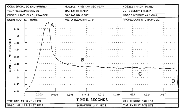
Figure 2-6. The thrust-time curve of an end burner. After an initial surge of high thrust, motor thrust drops back to a level where it remains constant for the duration of the burn. End burners are good for applications requiring low levels of thrust, and comparatively long burn times. Points A through D correspond to drawings A through D in Figure 2-3.
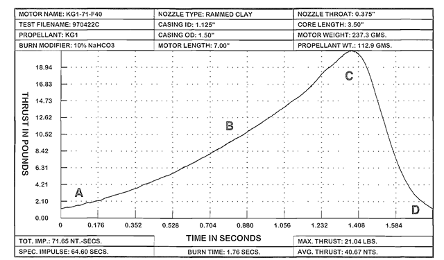
Figure 2-7. The thrust-time curve of a short cylindrical core burner. Immediately after ignition, motor thrust increases steadily, and reaches its maximum when the flame reaches the inside of the casing wall. At any given moment the remaining, unburned propellant acts as an insulator, protecting the casing from the hot flame until the final moments of the burn. The core burning configuration is therefore particularly well suited for the paper motor casings described in this topic. Points A through D correspond to drawings A through D in Figure 2-5.
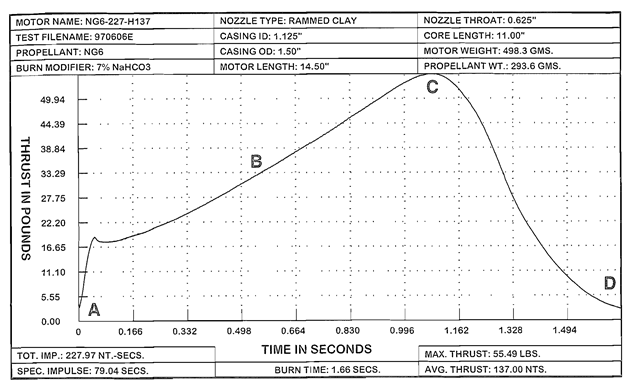
Figure 2-8. The thrust-time curve of a long cylindrical core burner. In this example, immediately after ignition, motor thrust increases to about a third of its maximum, and thereafter rises gradually. The high starting thrust makes a long cylindrical core burner a good choice for lifting a heavy pay load. Points A through D correspond to drawings A through D in Figure 2-5.
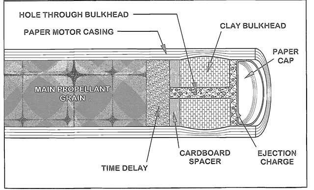
Figure 2-9. In an end burner, the beginning of the time delay is located at the forward end of the propellant grain.
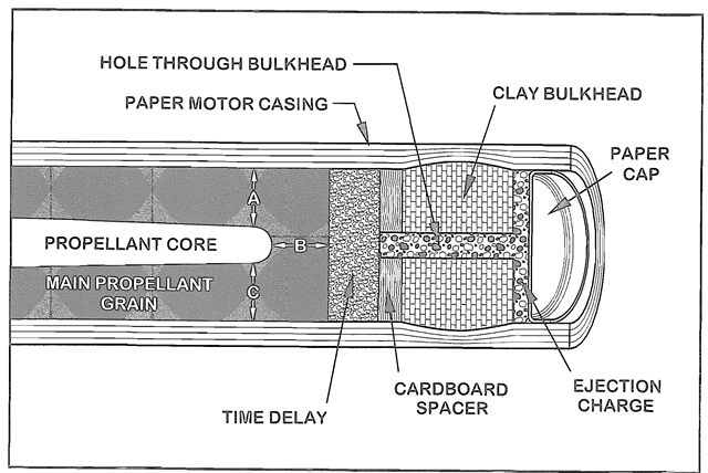
Figure 2-10. In a core burner, the beginning of the time delay is located at a distance ahead of the core equal to the propellants thickness between the front edge of the core and the casing wall. Distances A. B. and C should all be the same.
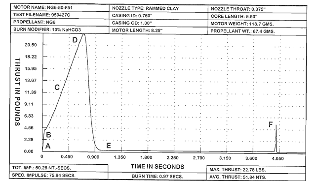
Figure 2-11. The thrust-time curve of a cylindrical core burner with a 3 second time delay and a parachute ejection charge. Points A through F correspond to the 6 drawings labeled A through F in Figure 2-12.
Time Delays (Rocket Motor)
Next post: Two Stage Rockets (Rocket Motor)
Previous post: Cylindrical Core Burners (Rocket Motor)
