Thrust, abbreviated F. is the pushing force generated by a rocket motor, and thrust may or may not vary during a motor’s operation. Whether or not it varies, and how much it varies depends on the motor’s design.
Burn time, abbreviated T, is a motor’s total time of operation from the beginning of thrust to the end of thrust.
Total impulse, abbreviated I. is the total amount of energy generated by a rocket motor from the beginning of thrust to the end of thrust. You can figure it out by breaking up a motor’s thrust-time curve (page 22) into a series of tiny thrust-time segments, and adding them all up (a process called “integrating” in Calculus). To work it out arithmetically you multiply the motor’s average thrust by its burn time. In the English system of measurement the total impulse is expressed in pound-seconds. In the metric system it is expressed in Newton-seconds. The metric-to-English conversion ratio is 4.45 Newtons per pound, so one Newton-second equals 0.225 pound-seconds.
Propellant mass, abbreviated mp. is the total amount of propellant burned during a rocket motor’s operation.
Average thrust, abbreviated Fa. is the value obtained by mathematically averaging a motor’s thrust over its entire burn time. To calculate a motor’s average thrust, you divide the motor’s total impulse by its burn time.

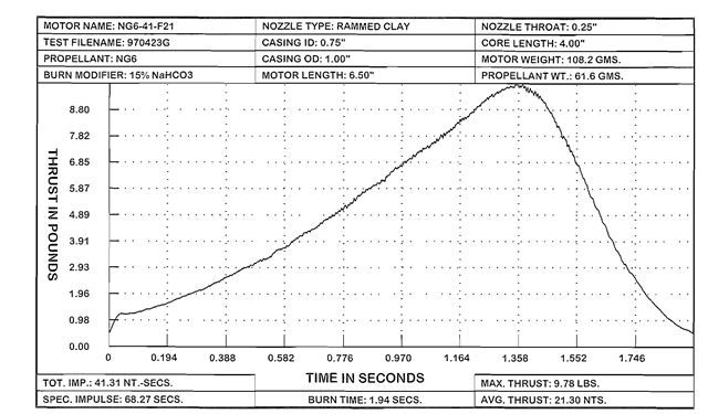
Figure 2-1. The thrust-time curve of an NG6-41-F21 rocket motor. A thrust-time curve provides the vital information needed to evaluate a rocket motor’s performance and predict what it will do during an actual flight.
Casing i.d. is the inside diameter of a rocket motor casing. In the motors in this topic, it equals the o.d. (outside diameter) of the propellant grain. In the time delay calculation on page 29.1 refer to the casing i.d. as “Dcas”.
Casing o.d. is the outside diameter of a rocket motor casing. The difference between a casing’s o.d. and its i.d.. when divided by 2. equals its wall thickness. The wall thickness is important because it directly effects the casing’s strength and how much operating pressure the casing can withstand. If the wall is too thin, it will rupture at normal operating pressure. If the wall is too thick, it unnecessarily increases the motor’s size and weight.
Motor length in this topic refers to the total length of a rocket motor’s casing, including the hollow volume in front of the forward bulkhead.
The nozzle throat is the narrowest part of the exhaust hole in a rocket motor’s nozzle. In the clay nozzles it amounts to a small, cylindrical passage, terminating at the beginning of the nozzle’s divergent taper. In the De Laval nozzles, to reduce friction and improve performance, this passage is shortened to a narrow, ring-shaped zone just wide enough to separate the convergent and divergent tapers.
Motor weight in this topic is the total weight of a rocket motor before it is fired. It amounts to the combined weights of all the motor’s parts, including the cardboard casing, the clay nozzle and forward bulkhead, and the propellant and time delay charge. Knowing a motor’s total weight is important when trying to predict how a rocket will perform during an actual flight.
A thrust-time curve is a graphic plot of how a rocket motor’s thrust varies with time. Thrust-time curves are useful because they provide the information needed to calculate important things like a rocket’s speed and altitude. For my own work I developed the standard form in Figure 2-1. This example illustrates the thrust-time curve of an NG6-41-F21 rocket motor.
Units along the horizontal axis represent the time in seconds from the beginning of thrust, and units along the vertical axis represent the thrust in pounds that the motor is generating at any given moment. The printed information above and below the curve provide all the motor’s vital statistics. To a trained eye. the size and shape of the curve combined with the other information provide an instant understanding of the motor’s capabilities. This data can then be used to compare one motor’s performance to another’s, or predict the flight performance of a rocket that is powered by the motor.

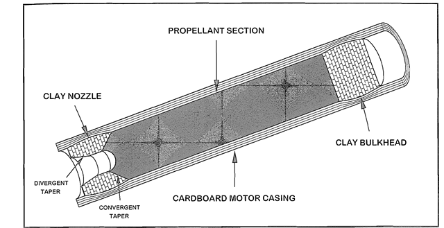
Figure 2-2. A cutaway drawing of an end burner. The propellant grain is a solid, cylindrical stick with its sides scale tightly to the casing wall. A dimple is formed in the rear end just large enough to accept an igniter.
Grain geometry is the term used to describe the shape of a rocket motor’s propellant grain. Because a propellant grain’s initial shape determines the path that the flame follows after ignition, a motor’s grain geometry determines what its chamber pressure and thrust will be during each moment of its operation.
Basic Terminology (Rocket Motor)
Next post: End Burners (Rocket Motor)
Previous post: Clay Nozzles (Rocket Motor)
