You can assemble this ignition system from common electronic and hardware items, and. as of this writing, you can buy most of them {Figure 17-14 ) at Pep Boys. Walmart. and Radio Shack. The system consists of a heavy power cable with a pair of battery clamps, a keyed rotary switch for arming the system, a red light to indicate when the system is armed, and a push-button switch that sends power to the igniter, and launches the rocket. The part numbers below are valid as of the year. 2003. As time passes, the numbers will probably change, but items that are similar will work. Important note. When buying the jumper cables, chose one of the cheaper sets made with copper wire, but thinner cable. If the cable is too thick, it won’t fit through the cable clamps and the other components used in the system’s construction.
MATERIALS LIST
1. One plastic Radio Shack 7″ x 5″ x 3″ Project Enclosure, cat. #270-1807 (or similar)
2. One Radio Shack “Jumbo” 12 volt lamp assembly (with bulb), cat. #272-336 (or similar)
3. One “300 amp” “Conduct-Tite” #85988 keyed auto battery isolator switch (sold at Pep Boys) (or similar)
4. One sealed 60 amp “Conduct-Tite” #85984 auto push-button starter switch (sold at Pep Boys) (or similar)
5. One set of automotive battery “jumper cables” (Walmart’s were the cheapest)
6. 5 feet of “audio”-type stereo speaker wire (looks like lamp cord, but thinner)
7. One 10 amp, 125 volt, 2-prong plug, and one 20 amp, 125 volt, grounded 3-prong socket
8. One package of Radio Shack “Mini” alligator clips cat. #270-380A (or similar)
9. Two 3/4″ cable clamps, plus the appropriate nuts, bolts, wire nut, and solderable wire-mounting lugs
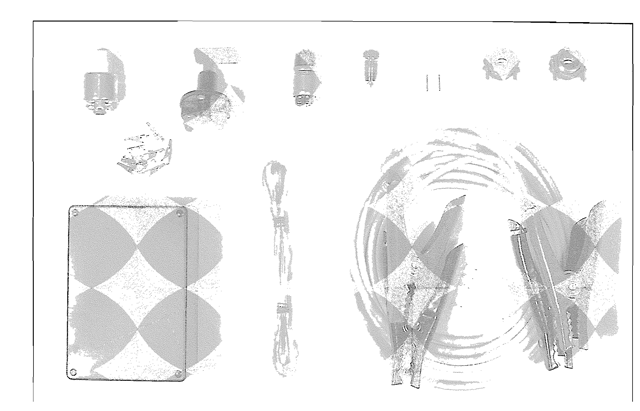
Figure 17-14. The parts for assembling a homemade ignition system. I bought most of them at Radio Shack. Pep Boys, and Walmart. I bought the wire, the plugs, and the cable clamps at a hardware store.
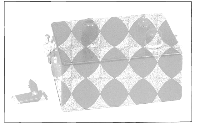
Figure 17-15. The plastic Radio Shack “project enclosure” with the keyed, auto battery isolator switch, the push-button ignition switch, and the 12 volt lamp assembly. For clarity. I’ve removed the red plastic key. and laid it next to the box.
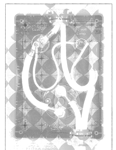
Figure 17-16. The wiring arrangement for the homemade ignition system. Up is toward the 3-prong socket, and down is toward the battety clamps. Use a good grade of electronic or PC solder for the soldered connections.
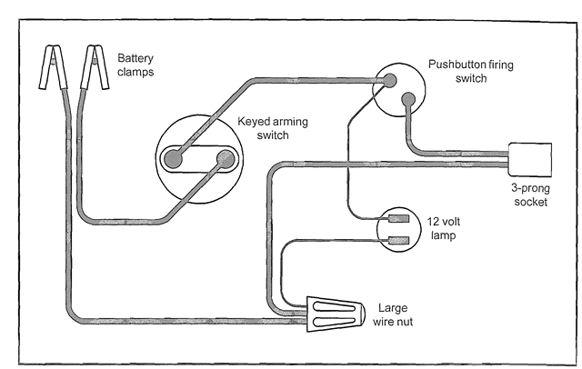
Figure 17-17. The wiring diagram for the homemade ignition system. Note. If you turn this diagram 90 degrees counterclockwise, it will look more like the photo in Figure 17-16.
1. In the plastic “project enclosure” (the plastic box), drill the appropriate-size holes for the lamp housing, the switches, and the cable clamps, and mount the various components as shown in Figure 17-15.
2. Cut the clamps from one end of the jumper cable set. Then from this cut end. take the pieces of cable needed for the box’s internal wiring, and the double wire leading out to the grounded 3-prong socket. Strip the ends of 2 pieces of this cable, and connect them to the 2 hot prongs of the 3-prong socket. Note that the socket’s round ground pin is not connected. You’re using a 3-prong socket, only because that’s what you’ll need to connect to the standard electrical extension cord that leads to the launch pad.
3. With a good grade of PC solder, crimp and solder on the necessary connector lugs, and make the connections shown in Figure 17-16. and the wiring diagram in Figure 17-17. Use thinner wire (i.e. 18 gauge) for the 12 volt lamp, and use a large wire nut to make the final connections shown at the right side of the photo.
4. Strip one end of the 5 foot length of speaker wire, crimp on a pair of alligator clips, and install the male, two-prong plug on the opposite end {Figure 17-18). Replace the cover on the “project enclosure” (the plastic box), and the ignition system is finished (Figure 17-19).
How to Use the Ignition System
1. Turn the arming switch off. and remove the red key from the switch. Then lift the car’s hood, and connect the battery clamps to the battery (Figure 17-20). Note that polarity is not important. Plug a standard 25-to-50 foot outdoor electrical extension cord into the system’s 3-prong socket, and walk the opposite end out to the launch pad. Then plug the 5-foot wire (with the alligator clips) into the extension cord.
2. Insert the igniter into the motor until it touches the front of the core (Figure 17-21). Make a short. L-shaped bend in the igniter leads. Tape them to the end of the motor with a single strip of masking tape (Figure 17-22). and set up the rocket on the launch tower. Then with the two alligator clips, connect the system to the igniter’s lead wires (Figure 17-23).
3. Walk back to the car. and insert the red key into the arming switch. Turn it clockwise until it snaps, and the red light comes on. indicating that the system is armed. Then push the black push-button to launch the rocket.

Figure 17-18. The 5 foot length of speaker wire with alligator clips and the male, two prong plug.
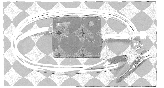
Figure 17-19. The finished rocket ignition system.
In Figure 17-23 you’ll notice something covering the connection between the alligator clips and the wire. When a rocket motor fires, it violently ejects the igniter, and in the process, the clips can be bent and broken off. To protect them, and make the joints between the wire and the clips last longer. I’ve covered them with two. short pieces of heat shrink tubing.
After a dozen or two firings, the 5-foot wire with the alligator clips will become burned and unusable, and you can replace it with a new one. I’ve tested this system with extension cords up to 75 feet long, and in every case it delivers a full 12 volts to the launch pad. and all the power needed for lighting the homemade igniters.
![tmp8B-5_thumb[1] tmp8B-5_thumb[1]](http://lh3.ggpht.com/_X6JnoL0U4BY/S2tFGKmD9eI/AAAAAAAANKc/f4Zpi8Y7tsQ/tmp8B5_thumb1_thumb.png?imgmax=800)
