14.3.
14.3.1.
Plug Screw Gauges.
For gauging nuts or internal threads it is obvious that full form plug gauge made accurately to minimum dimensions of internal thread will ensure that all dimensions of the thread are not less than that minimum if it will assemble with the thread.
Major, minor and effective diameters will be checked and it will ensure that size of pitch, angle or form of the threads is not reducing below minimum. It is not possible to judge individual error of a particular component. Strictly speaking a plain NO GO gauge is required for minor diameter, NO GO gauge for effective diameter and NO GO gauge for major diameter is also required. The NO GO major diameter gauge has its major diameter on the corresponding upper limit of the work with its flank and minor diameter being well cleared off the work dimensions.
In ordinary production practice, NO GO effective diameter gauge is the only one used apart from full form GO gauge. This gauge is all that is necessary to ensure that the threads of the work are not thin even though the major and minor diameters are within the limits. Since tolerances on major and minor diameters are larger than those on effective diameter, these can be easily controlled.
Form of threads for NO GO effective diameter gauge is shown in Fig. 14.1. It may be noted that NO GO plug is truncated and the roots of the threads are cleared away. This is done with a view to avoid

Fig. 14.1
contact with the crest of the mating thread which, while being large on the effective diameter, may have a minor diameter on the low limit. The truncations also avoid contact with the roundings at the root of the nut. The effect of all these modifications from full form is to limit the NO GO end of the gauge to checking only the effective diameter.
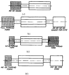
The gauges are made up of special quality gauge steel, hardened and seasoned before the threads are grooved and finally tapped to dimension. Plug gauges are made in different designs according to the purpose for which they are required. Most widely used patterns are shown in Fie. 14.2 (a), (b). (c) and (d).
For gauging parallel external screw threads, minimum of following 3 gauges are recommended.
(i) a plain caliper gauge with gauging features to check the tolerance on the major diameter.
(ii) a screw caliper gauge with full form gauging features to check the maximum effective diameter, or a screw ring gauge.
(iii) A screw caliper gauge with special gauging features to operate slowly on the flanks of the thread, to check the minimum effective diameter.
For gauging parallel internal screw threads, following 3 gauges are recommended.
(i) GO and NO GO plug gauges to check the tolerance on the minor diameter.

Fig. 14.2
(ii) a GO screw plug gauge to check the minimum effective diameter. (Hi) a NO GO screw plug gauge to check the maximum effective diameter.
14.3.1.1.
Notes on Screw Gauges.
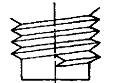
Since the entering surface of these is liable in service to become burred if placed too heavily on metal surface, the British Standard Institute has, therefore recommended that there should be a guard extension at entry as indicated in
Fig. 14.3. The extension is formed by reducing the diameter of end portion of the gauge.
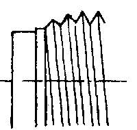
To minimise the risk of damage, the feather edges of all screw gauges (both plug and ring) of GO and NO GO types should be removed to the extent of one pitch so that thread at the end of gauge commences abruptly at its full section or with slight taper at the end.

GUARD EXTENSION ON PLUG GAUGES

METHOD FOR PREVENTING FEATHER EDGES
Fig. 14.3
Sometimes it is considered desirable to provide a dirt clearance groove in case of plug screw gauges. This groove is cut axial to the thread to a depth slightly below the root of thread, in a position where the thread commences its full section. The provision of such a groove on the gauge also prevents it from sticking. All sharp edges on gauging position as well as on handle should be removed.
In case of gauges above 100 mm diameter, lightening holes are advisable which enable the worker to handle them conveniently and also for venting purposes so that there is no risk of air being trapped in inner portion on blind hole.
14.3.2. Ring Screw Gauges.
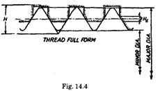
For production gauging of bolts the equivalent mating surface of the bolt threads is known as a ring gauge. As in case of plug gauges a system of limit gauges can be provided by full form NO GO and GO effective diameter ring gauges. The NO GO ring gauge is truncated on its minor diameter and cleared on its major diameter as shown in Fig. 14.4.
The first step in using a set of ring thread gauges is to read legend stamped on the rings. The legend should give size and pitch, for example, 7/16-20 NF means the workpiece should be of 7/16″ outside or major diameter having 20 threads per inch (National fine threads series). The pitch diameter upper limit is 0.4050″ which should also be stamped on the gauge. NO GO gauge member should also have same legend except diameter would be 0.4024″ (corresponding to lower limit). Sometimes class of fit also appears on the ring.
A thread ring cannot ordinarily be used to analyse the individual errors present in a screw. If the pitch diameter is over-size the ring will not engage : of course neither will it turn on an over-size major diameter. If the minor diameter is off (i.e., the screw whose roots are filled with dirt, or made from worn die or lathe tool) the gauge will bind. Excessive screw thread lead errors, like taper will ordinarily be detected after a few turns of ring gauge. Where very fine threads are being gauged, care must be exercised not to force the threads of the ring gauge on screw.
14.3.3. Caliper Gauges.
In principle these gauges are equivalent of gap gauges with thread form on anvils. In the metric system, external threads are gauged with a caliper type gauge with two sets of anvils. The front anvils have the full thread form cut on them and are set at such a distance apart as to accept the screws below the upper size limit, i.e., they are

the ‘GO’ anvils of the gauge. The width of these anvils is such as to test the required length of engagement of the screw so that they would reject a screw with a total pitch error over the length sufficient to raise the effective diameter to a value larger than anvils settings. If the screw passes through front GO anvils it reaches near NO GO anvils. There, NO GO anvils test the effective diameter, the tooth form on these anvils is cleared off at root and truncated at crest. They gauge one thread only as, their function will not be influenced by any pitch error in the screw being engaged.
Now if a screw is cut of correct effective diameter but has a pitch error, it will not be able to pass through GO anvils. The only way available except by correcting pitch would be to reduce its effective diameter. Then it will pass through GO anvils as well as NO GO anvils and will be finally rejected.
14.3.4.
Taylor’s principle applied to screw thread gauges
. It has already been indicated that effect of errors of pitch and flank angle is to bring about a virtual increase in the effective diameter in case of external threads and a decrease in effective diameter in case of internal threads. Accordingly Taylor’s principle can be applied to threads also. It may be remembered that according to Taylor’s principle, a GO gauge should check both geometric features and size and thus be of full form, whereas NO GO gauge should check only one dimension. In line with this, GO gauge is made of full form to the full length of thread to the maximum diameter of thread. If NO GO thread gauge is also made of full form, then the virtual reduction in effective diameter due to pitch errors may give misleading results.
To obviate this difficulty, and to account for Taylor’s principle, NO GO gauges for the threads are made to check for major diameter and the effective diameter which is not influenced by the errors in pitch or form of the thread.
