17.9.
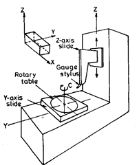
3-D measuring machines are very useful in modern sophisticated industry. These machines are designed for 3-dimensional calibration of certifiable accuracy. Fig. 17.23 shows the schematic diagram of such a machine. Such a machine is adaptable for computer control. Laser interferometers are provided as scales. A cooling system is incorporated to reduce the temperature rise when the machine is in operation. The workpiece (gauge) is mounted on the table which moves to provide the ^-measurement, ^-motion is obtained by movement of the large carriage (carrying probe on z-slide) across the bridge, z slide mounted on y-carriage moves vertically up and down. Axes movement is controlled by stepping motors attached to lead-screws. The three carriages are mounted upon double—V ways, the x andy slides with roller bearings and the z-slide with plain ways.
Fig. 17.23 shows a typical y-z measuring machine. The axi-symmetric part is centred upon the rotary table or the “c” axis. The rotary table is

Fig. 17.23. 3-D measuring machine.
mounted on the horizontal (y) slide. The electronic gauge stylus is typically a ball-tipped, single axis, linear variable displacement transducer (LVDT) carried and positioned by the vertical (z) slide. The axis of the LVDT is typically mounted at a 45 degree angle with respect of the y and z axes. A correction is provided for the cosine error introduced when the direction of travel of LVDT is not normal to the part surface.
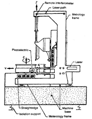
Displacement accuracy is achieved by laser interferometers operating in helium-shielded pathways. The interferometres are located in strict accordance with the Abbe principle, i.e., the extension of the laser interferometer axis passes through the centre of the stylus ball at its null position (the centre of stylus ball being “functional point”). Refer Fig. 17.24.
On the y-axis slide, two laser interferometers, suitably separated, are provided. The difference in readings between these two lasers is used as a servo input to drive a piezoelectric crystal that supports one end of they-axis table, thereby correcting the angular motion or pitch of the table.
Straightness accuracy is achieved by mounting straight edges parallel to each slide to measure and correct for slideway-straightness errors. For instance any error in the straightness of travel of z-slide will cause unwanted movement in they direction. The LVDT gauge head that contacts the straight edge detects this movement and corrects it by zero shifting the y-slide. Similarly when nonstraightness of y-slide travel is detected, the z-axis is zero shifted in the proper direction to correct the travel.
However stiff a machine may be made, it deflects and distorts owing to the effects of changing and moving loads on the structure. The metrology system must therefore be made
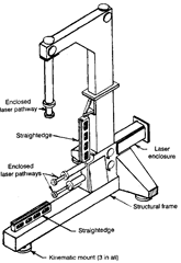
independent of the machine base, i.e., the external forces upon the metrology system must be constant. The metrology base is thus designed so as not to be influenced by the machine base (Refer Figs. 17.24 and 17.25). The frame is supported on kinematic mounts inside the machine base. The plane of the supports is coincident with the bending neutral axis of the machine base, and its influence on the metrology frame is thereby minimised. The metrology frame houses the laser, laser pathways and remote interferometers and also supports the two straight edges.
Because of low coefficient of expansion of granite, it is chosen for building the machine base. The base is supported on three pneumatic isolators. The metrology frame is built of steel because temperature-controlled oil shower is included.
For stability of the laser (which depends on the stability of the medium in the pathways), helium at a pressure slightly

Fig. 17.24. Conceptual drawing of cross section of 3-D measuring machine.
above atmospheric pressure (maintained at constant value by a regulator) is provided in pathways. The effect of helium pressure change on the laser wavelength is taken into account.
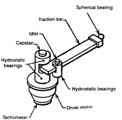
y-axis and z-axis slides ride on and are guided by hydrostatic bearings. A portion of each bearing is evacuated and the evacuated section acts like a vacuum chuck to hold the bearing against the way (similar to preloading the bearing). The balance of the bearing surface provides lift. They-slide support bearings are externally compensated to enhance the stiffness. The slide drive system (Fig. 17.26) can be considered as a rack and pinion drive wtihout gear teeth. The capstan is connected directly to the drive motor. The steel traction bar is squeezed between the capstan and the idler roller. One end of the traction bar is fastened to the slide with a spherical bearing. A coil spring supports the weight of the bar at the opposite end. Both the capstan and the idler are supported on hydrostatic bearings.
This type of drive system has minimum cost, minimum heat generation, maximum stiffness, minimum sliding friction, maximum linearity of displacement, no backlash, high reliability, compactness and minimum influence on slide straightness.

Fig. 17.25. Metrology system.

Fig. 17.26. Slide drive system.
The thermal environment of the measuring machine and the part is controlled by showering adequate quantity of oil controlled to 25°C. The shower is carefully sculptured to maintain machine temperature and to minimise splash. The primary advantages of liquid shower are its greater heat removal capability and the fact it is easily directed to the critical areas of the machine and workpiece surfaces. Liquids also have higher heat capacity than gases and accordingly it is possible to remove heat with corresponding lower temperature differences.
Three Dimensional Measuring Machine (Metrology)
Next post: Universal Measuring Machine (Metrology)
Previous post: Co-ordinate Measuring Machines (CMM) (Metrology)
