15.3.
A gear tooth is formed by portions of a pair of opposed involutes. Most of the terms used in connection with gear teeth are explained in Fig. 15.2.
Base Circle.
It is the circle from which involute form is generated. Only the base circle on a gear is fixed and unalterable..
Pitch Circle. It is an imaginary circle most useful in calculations. It may be noted that an infinite number of pitch circles can be chosen, each associated with its own pressure angle.
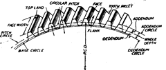
Fig. 15.2
Pitch Circle Diameter (P.C.D.). It is the diameter of a circle which by pure rolling action would produce the same motion as the toothed gear wheel. This is the most important diameter in gears.
Module. It is defined as the length of the pitch circle diameter per tooth. Thus if P.C.D. of gear be D and number of teeth N, then module (m) = DIN. It is generally expressed in mm.
Diametral Pitch. It is expressed as the number of teeth per inch of the P.C.D.
Circular Pitch (CP.). It is the arc distance measured around the pitch circle from the flank of one tooth to a similar flank in the next tooth. .-. CP. = nDIN = nm
Addendum. This is the radial distance from the pitch circle to the tip of the tooth. Its value is equal to one module.
Clearance. This is the radial distance from the tip of a tooth to the bottom of a mating tooth space when the teeth are symmetrically engaged. Its standard value is 0.157 m.
Dedendum. This is the radial distance from the pitch circle to the bottom of the tooth
space.
Dedendum = Addendum + Clearance = m + 0.157 m = 1.153 m. Blank Diameter. This is the diameter of the blank from which gear is out. It is equal to P.C.D. plus twice the addenda.
Blank diameter = P.C.D. + 2m = mN + 2m = m(N + 2). Tooth Thickness. This is the arc distance measured along the pitch circle from its intercept with one flank to its intercept with the other flank of the same tooth.
Normally tooth thickness = C.P./2 = nm!2
But thickness is usually reduced by certain amount to allow for some amount of backlash and also owing to addendum correction.
Face of Tooth. It is that part of the tooth surface which is above the pitch surface.
Flank of Tooth. It is that part of the tooth surface which is lying below the pitch surface.
Line of Action and Pressure Angle. The teeth of a pair of gears in mesh, contact each other along the common tangent to their base circles as shown in Fig. 15.3. This path is referred to as line of action. As this is the common generator to both the involutes, the load or pressure
between the gears is transmitted along this line. The angle between the line of action and the common tangent to the pitch circles is therefore known as pressure angle <|>. The standard values of <)> are 14.5° and 20°.
![]()
Base Pitch. It is the distance measured around the base circle from the origin of the involute on the tooth to the origin of a similar involute on the next tooth.

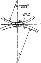
Fig. 15.3
Involute Function. It is found from the fundamental principle of the involute, that it is the locus of the end of a thread (imaginary) unwound from the base circle.
Mathematically its value is Involute function 8 = tan cb – <b
where § is the pressure angle.
The relationship between the involute function and the pressure angle can be derived as follows :
In Fig. 15.4, OA = base circle radius = Rb OP = pitch circle radius = Rp and BP = involute profile of gear tooth.
AP is tangent to base circle at A, Abe = <j) = pressure angle
Now OA = OP cos ()>, or Rb = Rp cos $
c6b = Involute function of
By definition of involute, length AP = arc AS
![]()
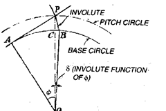
Fig. 15.4
Helix Angle : It is the acute angle between the tangent to the helix and axis of the cylinder on which teeth are cut.
Lead Angle : It is the acute angle between the tangent to the helix and plane perpendicular to the axis of cylinder (Refer Fig. 15.5).
Back Lash : The distance through which a gear can be rotated to bring its non-working flank in contact with the teeth of mating gear. (Refer Fig. 15.6).

Fig. 15.5. Illustration of Helix and lead angle.
Basic Tooth Proportions for Involute Spur Gears
| Pressure Angles | ||
| 20° | 14.5° | |
| Addendum | m | m |
| Dedendum | 1.25 m | 1.157 m |
| Teeth Depth | 2.25 m | 2.157 m |
| Circular teeth thickness | nm/2 | pm/2 |
| Fillet radius | 0.3 m | 0.157 m |
| Clearance | 0.25 m | 0.157 m |
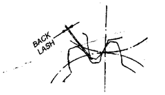
Fig. 15.6. Illustration of Backlash.
Some Important Relationships between Various Elements of Gears :
| To find | Having | Formula | |
| (a) Spur Gears | |||
| Module (m) | No. of teeth (N) and pitch diameter (D) | m | = D/N |
| Module | Circular pitch (p) | m | = pin |
| Outside diameter (D0) | Pitch diameter and Module | Do | = D + 2m |
| Base circular diameter (D6) | Pitch diameter and pressure angle | Db | = D cos <(> |
| To find | Having | Formula |
| (b) Helical Gear: | (Refer Fig. 15.7) | |
| Normal module (m„) | No. of teeth, pitch diameter (D) and helix angle (a) | D m„ = — cos a N |
| Normal module Normal circular pitch (p„) Normal Pressure Angle % (Refer Fig. 15.7) Lead Transverse teeth thickness (t) (c) Bevel Gears: Pitch dia. of pinion (Dp) |
Normal circular pitch (pn) Transverse circular pitch (p) Transverse pressure angle ($) and helix angle Pitch circle radius and helix angle Normal tooth thickness (tn), and helix angle (Fig. 15.8) No. of pinion teeth (n) and module |
pn=p cos a tan <t>„ = tan 4> x cos a L = 7t x D cot a t = <„/cos a Dp = n.m. |
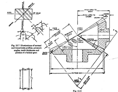
Face angle = Pitch angle + dedendum angle Root angle = Pitch angle – dendum angle
Fig. 15.9
| To find | Having | Formula |
| Pitch dia. of gear (Dg) | No. of gear teeth (AO and module. | Dp=N.m. |
| Pitch angle of pinion (pp) | No. of pinion teeth and No. of gear teeth | Pp = tan-1 n/N |
| Pitch angle of gear (Pg) | Pitch angle of pinion | Pg = (90-pp)° |
| Outer cone distance | Gear pitch diameter and pitch angle of gear. | Ag = Dg/2 sin Rg |
| (for pinion or gear) | ||
| Circular Pitch (p) | rn | jt = m x 7t |
| Dedendum angle | Dedendum of pinion or gear and outer cone | Ded. angle (p org) |
| for pinion or gear | distance | = Ded. (p or g)/Ag |
| Outside Diameter of gear (Da) | Pitch diameter of gear, addendum of gear and | DB = D + 2 addendum |
| pitch angle of gear | of gear x cos $g | |
| (g stands for gear,p stands for pinion) | ||
| Outside dia of pinion (da) | Pitch diameter of pinion (d), addendum | d„ = d + 2 addendum |
| of pinion and pitch angle of pinion | of pinion x cos Pp | |
| (d) Worm and Worm Gear : | ||
| Worm Lead (L) | No. of threads in worm (Nw) and axial pitch (px) | L=Nwxpz |
| Lead angle y | Lead (L) and pitch diameter (d) | tan v = L/ixd |
| Outside dia (d0) | Pitch dia (d) of addendum (a), | d0=d + 2a |
| Normal pitch (p„) | Axial pitch and lead angle | pn=pxxcosy |
| (i.e. in direction which | ||
| is normal to the thread) | ||
| Worm Gear (Fig. 15.9) | ||
| Pitch Diameter (D) | No. of teeth in gear (Ng) and axial pitch (of worm) | D = (Ngxpx)/n |
| Throat diameter (Dt) | Pitch diameter and addendum (a) | Dt = D + 2xa |
