2.3.
It is also known as scale. It is a line measuring device. It is the simplest and most common
measuring instrument used in inspection. It works on the basic measuring technique of comparing
an unknown length to the one previously calibrated. It consists of a strip of hardened steel having
line graduations etched or engraved at interval of fraction of a standard unit of length. Depending
upon the interval at which the graduations are made, the scale can be manufactured in different
sizes and styles. Various possible combinations of scales are found depending upon whether the
scale is graduated either on both sides and both edges or on edges of only one side. The scale can
be either 150 mm long or 300 mm or 600 mm or 1000 mm long. The scale need not be graduated
uniformly throughout its length. In some part e.g. it may have 10 divisions of centimetre, in some
portion 20 divisions, so that it can be used for all types of work and the particular range chosen
depending upon the accuracy required.
Certain scales have got some attachments and special features with them to make their use
more versatile e.g., very small scales may be provided with a handle to use it easily. They may be
made in folded form so that these can be kept in pocket also. Certain scales take into account the
shrinkage of materials after cooling and are called shrink rules. These are used in foundry and
pattern making shops. Scales can also be attached with an adjustable shoulder to make them
suitable for depth measurement.
2.3.1.
How to use scale.
It is very necessary that for getting good results, certain techniques
must be followed in the use of scale.
(1) Generally the scale is worn at the ends. Therefore, the end of the scale must never be set
with the edge of the part to be measured. This is not only because end scale is usually worn but also
it is very difficult to line up the end of the scale accurately with
the edge of the part to be measured.
(2) The scale should never the laid flat on the part to be
measured, because by doing so the graduations of the scale are
not in direct contact with the surface of the part and it is
difficult to read the correct dimension.
Some of the desirable qualities of the steel rule are: good
quality spring steel, clearly engraved lines, graduations on two
edges, and minimum thickness.
In using a rule the principle of common datums should
be employed. This principle is shown in Fig. 2.1, the set-up
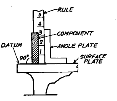
Fig. 2.1. Engineer’s steel rule.
indicating the correct method of measuring the length of a component. A surface plate is used as a
datum face and its purpose is to provide a common location or position from which the measurement
can be made. It is important to note that both the rule and component are set perpendicular to the
working surface of the surface plate, and the use of an angle plate simplifies the set up.
The degree of accuracy when measurements are made by a steel rule depends upon the
quality of the rule, and the skill of the user in estimating part of a millimetre.
The engineer’s rule, used for making direct measurements, depends upon visual alignment
of a mark or surface on the work to be measured against the nearest division on its scale.
Various errors in measurement can be minimised by using a rule whose thickness is as small
as possible.
It is important when making measurements with an engineer’s rule to have the eye directly
opposite and at 90° to the mark on the work, otherwise there will be an error—known as
‘parallax’—which is the result of any sideways positioning of the direction of sighting.
In Fig. 2.2, point P represents the mark on the work whose position is required to be measured
by means of a rule laid along-side it. The graduations of measurement are on the upper face of the
rule, as indicated.
If the eye is placed along the sighting line P which is at 90° to the work surface, a true reading
will be obtained at ‘a’, for it is then directly opposite to P.
If, however, the eye is not on this sighting line, but displaced as at B or C, then an incorrect
reading will be obtained.
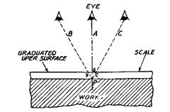
Fig. 2.2. Possible errors with direct eye
measurement.
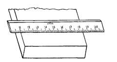
Fig. 2.3. Recommended method of
using scale.
Best way of using the scale is as shown in Fig. 2.3, i.e. the scale should be made to stand on
the part and 1 cm graduation coinciding with one edge. Then scale should be kept parallel to the
edge of the part. The accuracy obtained now depends upon the user’s ability to read the graduation
which most closely coincides with the other end of the part. The proper scale should be chosen
depending upon the accuracy desired. If the edge lies between two graduations and it is more than
midway of two divisions, the next higher division must be read.
Sometimes it becomes necessary to use one end of scale in the measurement of certain parts,
e.g. a circular bar having collar at one end. In that case a new scale must be used and end of scale
held firmly against the collar. In order to obviate the difficulty of end being worn, sometimes a hook
is provided at the end of the scale. The inner surface of the hook coincides with zero reading of scale.
The hook is held against the flat portion of piece and readings taken. Such a scale is called-hook
scale.
Since the edges of a scale are important in measurements, it should never be used for cleaning
between parts or as a substitute for the screw driver. The sharpness of graduations must be
maintained by the use of grease dissolving fluids.
2.3.2.
Measuring from reference point to measured point
. Any linear measurement
can be broken down into two points, the reference point and the measured point, and we measure
from reference point to the measured point by setting the instrument first on the reference point
and then reading along it until we find the measured point.
There is always an uncertainty in measurement derived from an attempt to strictly and
sufficiently define the geometric characteristics of a physical object. The act of measuring ensures
the possibility of error in that assessment or description. Understanding the relationship between
form and position ensures the proper use of a measurement system to assess and describe geometric
relationships.
Measuring the diameter of a hole with a steel rule clearly establishes the above principle.
The 1 cm mark on rule is the reference point. The rule is carefully set on one point of the
circumference of the hole so that it can be pivotted about 1 cm mark. To locate the measured point,
the rule is swung back and forth slightly along the arc of the hole opposite the stationary 1 cm
mark—the 1 cm mark acting as the pivot or hinge-until the opposite point on the longest chord is
located. Thus diameter is correctly measured and read.
The test of measurement is repetition, i.e. repeated readings that are the same. If same
dimension is measured several times and different readings are obtained, then measurement is not
being taken accurately, there being something wrong with the measuring instrument or the
measuring procedure.
2.3.3.
Folding Steel Rule.
Folding steel rule has two or more graduated lengths of steel
connected together by swivel joints, with square datum ends. It consists of legs of approximately
equal length, connected end to end by permanent joints to form a straight line. Both extreme ends
of the rule are flat and square to the rule edges.
The joints locate the legs in a straight line during service and also allow the rule to fold into
a convenient length.
Both ends of the rule are sometimes fitted with tips within the graduated length. The tips
are of the same width as the rule and fit flush with the rule end and edges. These tips are securely
fastened to the outer face only of the appropriate legs.
Accuracy requirements.
Flat ends of rule are square with the rule edges to within 0.05
mm over the width of the rule. Each joint ensures the alignment of the graduated edges of its two
associated legs to within 0.25 mm. It also locates the positional continuity of the graduation to
within 0.2 mm. Each individual leg of the rule is accurately graduated with a maximum permissible
error between the centre lines of any two graduation lines on a single scale in accordance with
permitted tolerances. The positional error of the centre line of the first and last 10 mm graduation
lines relative to its nearest square end does not exceed 0.1 mm.
2.3.4.
Graduated Rule Accessories.
In the use of graduated rules for direct length
measure-ment, the reliability of measurement is directly related with the proper positioning of the
rule in relation to the workpiece. Several accessories are available to help improve the accuracy of
the rule positioning.
(i) Hooks. These are used to provide a good alignment of the zero point on the scale with
the border line of an object surface, and also to keep the rule in a position substantially normal to
the edge of that surface. These may be of fixed length or extendable type, reversible and removable
type. These are mounted on the ends of steel rules as shown in Fig. 2.4.
(ii) Clamping Shafts. These are used to hold short rule sections to permit direct measure-
ments in cramped-locations, where the space confined within the walls of the feature does not
provide access for regular size rules.

Fig. 2.4. Use of hooks to align the starting point of the rule
graduations with the edge of the object.
(iii) Parallel clamps. These are used for aligning steel rules with the axis of cylindrical
shafts.
(iv) Foot rests. These permit graduated steel rules to be held in a substantially vertical
position with the starting point of the scale graduations on the support level of the foot block.
(v) Square heads and centre finders. These are used in layout work. Centre finders are
used on steel rules to permit scribing centre lines on the face of round objects. Square head aligns
rule normal to the edge of a straight sided object.
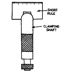
Fig. 2.5. Used for measuring in cramped areas.
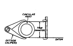
Fig. 2.6. Use of outside calipers.
