17.5.
Fundamentally projection comparator (projector) is a measuring instrument which projects an enlarged shadow of the part being measured on a screen, where it is compared to a master drawing. By this device, complicated shaped parts can be easily checked. In any projection system, there are four essential elements, viz., source of light, collimating or condensing lens, projection lens and screen. The illumination required for any projector is a parallel beam of light, which can be achieved if the source of light is a point source and is placed at the principal focus of the collimating lens. The purpose of collimating lens is to render the
beam of light from point source parallel. The projection lens consists of a system of lenses which form a real image on the screen of an object placed between it and collimator. The screen is generally translucent so that the image can be viewed from the opposite side.
17.5.1. Horizontal Projector.
This was designed by N.P.L. and is the earliest form of projector. It consists of a base casting. A lens system and a sliding carriage carrying the object to be projected are mounted on the base. The carriage slides parallel to the optical axis and this enables the object to be focused. The disadvantage with this is that there is only one plane normal to the optical axis in which all sharply focused parts of the object must lie. The lamp housing and collimation lens are carried on two bars arranged to pivot about a vertical axis passing through the projection lens to enable the collimating beam to be inclined to the optical axis for projection of screw threads. Its magnification is of the order of x 50.
17.5.2. Vertical Projector.
The horizontal comparator is not suitable for rapid inspection of small work and also it occupies more space. In vertical projector, the optical axis from the projection lens rises vertically and is reflected down again from a mirror on to a small horizontal screen. It has the advantage of occupying less floor space, the work is near the screen, and therefore the size of screen is also less. The horizontal screen enables user to stand and view the image conveniently. The profile drawings and templates can also be laid down conveniently without the necessity of fastening with tape etc. The illumination is obtained by a carbon arc in conjunction with a long focus collimator.
17.5.3. Cabinet Projector.
The various advantages and conveniences of projection as a method of inspection have led to the development of a self-contained type of projector. It is now available in compact form and can be used anywhere. Some of the projectors available commercially are discussed here.
17.5.4. Bausch and Lomb Projector.
The various parts are explained here in detail to understand the principle.
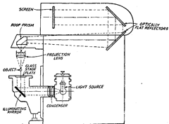
The optical system of this projector is shown in Fig. 17.3. This is discussed under two
heads, illuminating system and projection system.
The illuminating system consists of a light source, a tungsten arc lamp. The glowing element in the lamp is a small cylinder of tungsten which is heated to in-condescene by
electron bombardment. It is enclosed in a ventilated lamp-house. The light from the lamp passes to a system of lenses called achromatic condenser. With single lens condensers, the screen

Fig. 17.3. Optical System of Bausch and Lomb Projector.
image consists of various colours. So to get rid of them, each lens assembly is composed of two kinds of glasses. The parallel beam of light from the condenser is then transmitted to the illumination mirror, which sends the beam vertically upward, through the glass stage plate in the worktable, past the object.
The projection system consists of the projection lens, roof prism, a pair of image reflectors and screen. The magnification of the projector can be adjusted by changing the projection lens assembly. The adjustments for changing the lens assembly are very easy and accurate. It is done by merely placing the assembly into the bracket. The light travels past the object to the projection lens from which it passes upward to the roof prism. The function of the roof prism is to direct the beam of light horizontally towards the back of the projector to assist in the projection of the image so that its aspects presented to the observer are correct. From the roof prism the light passes to two optically flat reflectors which change the direction of the beam of light and direct it horizontally to the screen.
When an observer looks the image, he will find the image as erect and its aspects same as that of the object, i.e., movement of an object in any direction on worktable will cause a corresponding travel of the image. If the object is moved to right or back, a corresponding movement of image to the right or up will be observed.
17.5.5. Societe Genevoise Projector.
This is a comprehensive measuring machine intended for the measurement of objects like gear cutting hobs and other complex tools. The work is held in the centres. For the spacing of every tooth, there is a headstock fitted with a dividing head. The longitudinal movement of the carriage is measured by a precision scale and microscope. The various types of indicating units can be set up for radial, longitudinal and transverse measurements, thus covering the measurement of any complicated shape. In this way in a gear hob cutter, the flute spacing, tooth relief concentricity etc., can be directly checked and the form and angle of teeth can be measured by projection.
17.5.6. Screw Thread Projection.
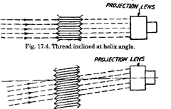
In projection of a thread a part of the helix always crosses over in front of each part of the thread and interferes with the direct passage of the rays. This can be overcome by either inclining the axis of the thread at an angle equal to the
helix angle so that the collimated beam gazes the thread without appreciable interference or by inclining the collimated beam to the helix angle by swivelling the lamp house about a vertical axis passing through the projection lens. The image formed on the screen is that of a plane cutting the thread normal to the helix and lying at an angle to the axis. In second method, the axis of the threads lies in the plane of the axis and hence defined profile is produced without loss of field and definition. The projection lens must be well designed, otherwise only small helix angle can be dealt with. In case of first system, the arrangement is very simple.
It is found that difference in profile between the two methods is generally difficult to be detected and hence first method which is more convenient is used.

Fig. 17.5. Collimated beam inclined (Projection of Axial section).
The advantages of thread inspection by projector are :
(1) It simultaneously compares all the elements of the thread with an accurate gauge.
(2) Right hand and left hand threads as well as wide range of diameters and pitches, can be measured.
(3) It eliminates the cost and uncertainty of gauge wear and is an inexpensive method.
(4) It is a rapid and more positive method.
17.5.7. Use of Standard Radius Chart and Standard Centreline Screen.
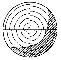
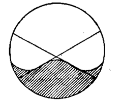
A big advantage of optical contour projector is that it readily permits checking of dimensions from points and lines not located on the surface of the workpiece, like centres of holes, the intersections of two straight lines which are the expansions of rounded corners, the radius, centre of a fillet, etc. Fig. 17.6 shows the use of standard radius chart to locate the radius and centre of a fillet. Fig. 17.6 shows the use of a standard centre line screen to find the point of intersection of two sides where a corner has been rounded.
17.5.8. Checking of Profiles which can’t be Projected.
A special tracer unit on optical contour projector permits checking of internal or hidden contours which can’t be projected on the contour screen. A ball tipped tracing stylus is moved over the part contour while an identical ball moves through an identical path at the end of a pantograph and the movement of other ball is projected on the screen where the enlarged desired internal contour is fixed up. The shape of the stylii is chosen properly depending on the kind of internal contour.

Standard Radius Chart

Standard Centreline Screen
Fig. 17.6
17.5.9. Precaution in the Use of Optical Projectors.
The workpiece should be so located on the table in the path of the projected light beam, and light and lens so focused that double shadow of false, silhouette edge and other abberations are avoided as far as possible. Dust, moisture, oil etc., should not be allowed to colled on such apparatus.
