6.12.
In linear as well as rotary measurements, the grating (scales with a continuously
repeating pattern of lines or grooves) play an important role. The gratings may have line
spacings from 4 to 200 per mm, in lengths up 4 metre or so. These may operate by reflection
(in which case the strips approximately equal in width are alternately reflecting and non-
reflecting), or by transmitted light (in which case the strips approximately equal in width are
alternately opaque and transmitting), and are usually employed with photoelectric readouts.
As Moire scale is long and continuously ruled one having repeating pattern of lines, it is not
necessary to separately indentify individual line or groove, i.e. have absolute measurement,
but incremental measurement is best in this case. The position with Moire scale is sensed by
the average of about 50 to 100 lines, and thus if a single line is out of place among 1000 accurate
ones, the effect is reduced by a factor of 1000. In this scale, the response speed of the
photodetectors (counting devices employed) limits the rate at which the positional information
can be obtained.
Amplitude grating (also known as Ronchi rulings) is one which has plane lines, and the
prismatic or phase grating is one which contains triangularly shaped, contiguous grooves. The
latter type has 100 to 200 grooves per mm and its length is limited to 250 mm.
Moire fringes (a series of parallel bands, alternately dark and bright) can be observed
by placing two similar continuous-type scales of gratings face to face, or nearly so, with their
lines nearly parallel. The Moire fringes are readily visible to the naked eye. Distance between
fringes depends on line spacing and the angle between the pair of gratings. For measurement
purpose, one grating (index grating) is kept stationary and the other grating is moved over it
in a direction perpendicular to the lines. When doing so, one can see the fringes moving at right
angles to the motion of the scale and at a rate corresponding to exactly one fringe for a motion
of one scale interval. As the Moire fringes are quite coarse particularly if scale with 40 lines
per mm or coarser is used, relatively simple optics can be employed to watch Moire fringes.

Fringes of high intensity (good contrast) can be obtained (which is essential condition
for obtaining good electrical signals) only when the distance between the scale and index
grating is minimum possible. The problem is not so severe for coarse gratings but it is found
that for fine prismatic grating, distances (spacings) as low as 0.001 mm may be required for
’200 lines per mm rulings. This condition can be achieved very easily by dispensing with the
index grating altogether and arranging an optical system that images a scale back upon itself.
This not only fulfils the above condition of very low spacing, but twice as many fringes are
produced for a given scale motion, and further the fringe pattern is not affected by slight
rotation about an axis normal to the scale.
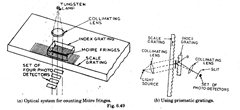
As already indicated, for bi-directional fringe counting, two photocells spaced 90 fringe-
phase degrees apart are adequate ; however, it is found that in practice better balance is
obtainable with four detectors placed at 0, 90,180 and 270 fringe phase degrees in which case
counting intervals of one-quarter of the scale interval are provided.
When using prismatic grating, diffraction properties of such a grating must be con-
sidered for maximum efficiency ; the optimum arrangement being obtained for minimum
deviation position [Refer Fig. 6.49 (&)]. Considering the central ray, it is split mainly into two
approximately equal parts, one passingthrough straight undeviated, (zero order) and the other
is diffracted by angle 9, depending on the grating spacing and wavelength of the light. It may
be noted that scale grating and index grating are arranged with the grooves in opposition. With
this arrangement, the first zero order ray on striking the index grating surface is diffracted in
the first order direction whereas the first-order ray (i.e. the deviated one earlier) now goes
through undeviated through index grating as the zero order. Thus both the rays are rendered
parallel and these rays of equal intensity interfere with each other to form Moire fringes with
nearly pure sinusoidal intensity distribution.
6.12.1.
Photoelectric scale viewing system.
The various advantages of photoelectric
scale viewing systems are :
(i) Eyestrain is eliminated, as output is in
the form of digital signals.
(ii) High precision obtainable (0.01 mm.)
(iii) Total carriage movement is measured
directly, and intermediate drives such as lead
screws, ball screws, rack-and-pinion devices, etc.,
are not required.
(iv) Setting can be done precisely and
preset facilities exit for setting datum at any
point relative to desired position.
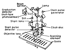
In this system, two or three scales (espe-
cially designed for the purpose—having fine
graduations, coarse tracks, lines of varying thick-
ness along the scale etc., etc.) are mounted on the
member whose movement is to be measured. The
scales are so designed that when viewed through a rotating clock disc having alternate opaque
and transmitting lines, then for every position of the scale, separate digital signals will be
generated which can be interpolated and calibrated in terms of the increments of movement
of length. Referring to Fig. 6.50, the position of the scale is continuously scanned by a rotating
clock disc in front of an objective which images the line on to a pair of photodetectors. Alongwith
the scanning, the pulses are generated in phase synchronism. The pulse duration corresponds
to the least scale interval. The system also incorporates a device for starting the interval
counting sequence once in each revolution. As a result of all this, a digital interpolation of the
scale interval is obtained which is supplemented by information from the set of coded tracks
(scales), and thus each scale interval is identified in a digital form.
6.12.2.
Types of gratings used in Moire Fringe System of Measurements
Three types of gratings commonly used in Moire Fringe System of the measurement are
(i) Phase transmission grating, which is normally produced on selected glass blanks.
(ii) Metal reflecting grating, which is used for travel length greater than 1800 mm.

Fig. 6.50. Photoelectric scale viewing system.
(iii) Line and space transmission grating. It includes the widely used 40 lines/mm variety
which are reproduced photographically on glass.
The optical systems used also differ depending on the type of grating used.
Source of errors
The main sources of errors in measurement by moire fringe system are
(i) Grating error lg. It can be taken as the calibration specification limit for the length
and type of grating in use which is given for 99% confidence level.
(ii) Digital error Ij.
(iii) Analogue sub-division error la. It arises from tolerances in the d.c. level of signals
from the reading head and in the analogue to digital converter stages. Its value is taken as
0.05 of grating pitch for glass transmission gratings and 0.08 for steel reflecting gratings.
(iv) Mechanical errors—lm. Since each measurement involves two settings, it is neces-
sary to add twice the square of first three errors to assess the accuracy of the measuring system
by computing R.M.S. value.
![]()
6.11.3.
Leitz System.
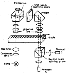
Fig. 6.51 shows in schematic form the arrangement adopted in
an optical system using a linear transducer made by E-Leitz, Wetzlar. Light from a lamp passes
through a condenser lens and red filter on
to the scale. The image of the scale is
deflected by the pentaprism through a
beam splitting prism, which produces
two sets of scale images, displaced rela-
tive to each other and polarised at 90°.
Both images are reformed in an identical
position on the scale surface by the action
of a prism and objective lenses but are
displaced to each other by 0.25 of the
scale division width. Measuring errors
cannot creep in since the light forming
both images is the same.
When the scale is moved lon-
gitudinally, the images of the scale travel
in the direction opposite to that the scale
movement. The light beams comprising
the scale images also pass through the
scale to the second beam splitting prism,
which separates the signals according to
their direction of polarisation and reflects
them through condenser lenses to the
photocells Pi and P2-

Fig. 6.51. Leitz system.
As the images traverse the scale markings, the intensity of light reaching the photo-cells
is modulated, and the phases of the electrical signals produced cover 0.25 of a scale division
width. Analogue signals corresponding to half the scale division width are thus obtained, and
these signals can be divided electronically into 200 parts.
The intensity of light from the lamp is ensured at a constant value by sensing same by
another photocell and varying the gain of the amplifier by a feedback circuit.
