3.5.
For all practical measurements in workshop, we employ end standards e.g. slip gauges, gap
gauges, end of micrometer anvils etc. Thus the importance of end standards (which are actually
used in general measurement applications) arose. Length bars and slip gauges were then made
which were equal in length to the legal line standard. The only difficulty realised with end standard
was that of forming two accurately parallel surfaces at the end of a bar and to heat treat the ends
so that they remained stable.
3.5.1.
End Bars or Length Bars.
These are used for the measurement of larger sizes of
work. These consist of carbon steel round bar about 20 mm in diameter and made in sizes varying
from 10 mm to 1200 mm. These are hardened only at ends upto 800 HV and supported at ‘Airy’
points so that end surfaces are parallel to each other. For bars above 150 mm size, the airy points
are indicated by pairs of circumferential lines inscribed around the bars. Such bars are used for
standardising the normally used one inch bars in combination. These are, therefore, generally not
found in majority of engineering works but in standardising laboratories etc. These are also
available in four grades of accuracy (i) reference, (ii) calibration, (Hi) inspection, (iv) workshop.
Workshop and inspection grades have internal threaded ends and can be used in combinations with
the help of a standard stud.
Slip gauges are also used as end standards of measurement in all metrology laboratories.
These are made of high grade cast steel and hardened throughout. With the set of slip gauges,
combination of slip gauge enables measurements to be made in the range of 0.0025 to 100 mm but
in combination with length bars measurement range upto 1200 mm is possible.
3.5.2.
Transfer from Line Standard to End Standard.
It has already been clarified that the line standard of length is a highly inconvenient form for general measurement applications. In order to determine the position of the defining lines in the standard, a special microscope has to be
employed. Since the line standard was defined first, and end standards being of real importance
and more utility ; the end standards had to be produced of the highest accuracy in relation to the
line standard. In end standards, the distance is defined between the working faces which are flat
and mutually parallel. In order to transfer the line standard correctly to the ends of a bar, the use
of an instrument called Line-standard comparator is made. It consists of two microscopes mounted
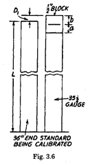
about a yard apart over a table. A gauge, about 35 | inches in length is produced with end faces
flat and mutually parallel. Two | inch blocks are taken and wrung at the ends of this gauge. The
two | inch blocks are engraved with a fine line on one surface approximately in the centre of the
two end faces. Thus the distance between the centre lines is approximately 36 inches after wringing
these | inch blocks to the main 35 ~ inches gauge.
The standard and the above blocks are mounted on the table. The microscopes have accurate
micrometer screw controlled eyepieces. In eyepiece, there are cross wires to focus on the lines of the
standard. The table is capable of being traveresed across so that either block may be brought under
the microscope. The apparatus compares the positions of lines on the standard with lines on the
gauge, and with micrometer eyepieces any small longitudinal variations between them can be
determined.
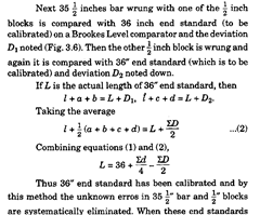
Let the actual length 35^ inches gauge be /. The distance between two lines on line standard
is 36″. Let us ignore the effect of the wringing film between the surfaces in contact as it is always
present in the use of end bars and gauges. The other possible erros are the misplacing of the line
at the mid-position of the end faces of ^ inch blocks and possible error in the length of 35^ inches
gauge. The two blocks at end are arranged in four ways. (Fig. 3.5 shows one position and other three
positions are self-explanatory) and difference of readings between lines on standard and the line
on gauges are noted every time. Let the difference be dh d2, d3 and rf4 respectively. Then for the
successive positions of the | inch blocks, we have

![]()


are calibrated in this way, these are used as master gauges from which further sub-divisions are
obtained e.g. two 18″ gauges may be prepared and when wrung in combination, their length is
compared with that of 36″ end standard master gauge.
Again they are compared amongst themselves as the previous error is in both of them and
need not be equally distributed. Thus individual errors of the 18″ gauges can also be isolated. A
similar procedure is used to determine the length of any smaller gauge, in terms of 36″ master
gauge.
3.5.3.
Sub-divisions of the End Standard by Brookes Level Comparator.
Brookes level
comparator consists of a very accurate spirit level. The spirit level is supported on balls so that it
makes only point contact on gauges. First the table on which gauges are to be compared is levelled
properly by spirit level. Then the two gauges to be compared are wrung on the table and the spirit
level is lowered on them. After it the position of bubble is noted down and table rotated by 180° so
that position of two gauges is interchanged. Again spirit level is lowered down on gauges and the
bubble reading noted (Fig. 3.7). If the two gauges are not of equal length then two readings will be
different and effect of interchanging the position of the gauges will be to tilt the level through angle
equal to twice the difference in the height of gauges divided by the spacing of level supports. The
difference of gauges will, therefore, be equal to half of the above height difference. The bubble
readings can directly be calibrated in terms of the height difference as the distance between the
two balls is fixed. The advantage of turning the table by 180° is that the effect of table not being
level initially is eliminated. Thus for other smaller gauges, they may be combined to form 36″ master
gauge and then compared amongst themselves. This sub-division in similar way can be more
accurately done by interferometry method to be discussed later.

Fig. 3.7. Brookes level comparator.
Since we are interested here in extremely fine measurement, an important attention is
required to be paid to keep the temperature of the room constant as most of the metals suffer slight
changes in length when subjected to variations in temperature. It is, therefore, desirable that room
must be kept at 20°C by thermostatic control and sufficient time must be allowed for the room and
the gauges to attain steady temperature.
3.5.4.
Comparison of an end gauge with a line standard by the displacement method.
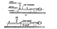
The set up for this is shown in Fig. 3.8. It utilises tool room microscope for small specimen
and horizontal microscope for longer specimen.

Fig. 3.8. Displacement method.
The line standard is placed on a carrier and adjusted to bring the lineXunder the cross-wires
of the fixed microscope. The micrometer spindle is rotated so as to bring it in contact with the
projection on the carrier and micrometer reading noted. The carrier is then moved along to bring
the line Y under the microscope crosswires and the end gauge is inserted as shown in Fig. 3.8 (b)
and the micrometer reading is noted again. The length of the end gauge is equal to the length of
the line standard plus the difference between the micrometer readings.
