10.4.
As a result of handling in the laboratory or inspection room, slip gauges are liable to exhibit signs of wear after appreciable period of use and should, therefore, be checked or recalibrated at regular intervals. This can conveniently be done with the aid of a millionth measuring machine such as the Newall interferometer.

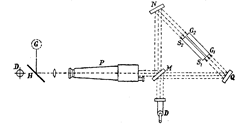
Fig. 10.13. Infererometer.

(a) (b)
Fig. 10.14. Checking slip gauges with interferometer.
The gauge comparison and absolute measurement are done by an interferometer. Plan and elevation of this instrument are shown in Figs. 10.13 and 10.14. It consists essentially of a Higler interferometer arranged in such a way that both the ends of the gauge being tested are examined simultaneously in the same field of view. After simple adjustment, the gauges show interference fringes across the faces at both ends and from the relative positions of these differences in length can be measured to accuracy of 0.00002 mm. For all lengths to be tested by the instrument, the reference gauge and the gauges being tested are placed side-by-side and the optical system adjusted to give, with white light, a pattern of interference fringes across the face of the gauges. The illumination is then changed to different light of three or four different wavelengths, one after the other from the monochromatic source ; the position of the interference fringesl)eing noted each time. The absolute length is then computed with the help of the special slide rule provided for this purpose.
10.4.1.
Description of the Instrument for Checking Slip Gauges.
A dual collimator A, with a white light source B and slit C provides white light; and a monochromatic light source D, condenser E and slit F provide monochromatic light. An alternative monochromatic light source G may also be employed and introduced when required by the mirror H which can be swung in and out so that either light source D or G can be selected. The monochromatic light is reflected by the mirror J to the depression prism K. This mirror can be rotated by the micrometer L to select suitable wavelengths, which are engraved on the micrometer drum. The prism K can be swung in or out of the optical axis, so that white light or monochromatic light can be transmitted to the interferometer. This light is transmitted to the dividing mirror M and some of it is reflected to the mirror N from where it is turned towards the end faces of the gauges. The light is then reflected back along a similar path to the observing telescope P. Some of the light transmitted by the dividing mirror goes to the mirror Q from where it is turned to the opposite end faces of the gauge and reflected back to the observing telescope.
10.4.2.
Comparison of the Lengths of two Slip Gauges.
The two gauges are mounted side by side as shown in Fig. 10.13 and both ends of each gauge are observed through the telescope, but the mirrors are so arranged that the end faces of the gauges appear to overlap each other as shown in Fig. 10.14. For clearness, the end faces are shown displaced vertically in the illustration.
The standard gauge S is adjusted so that the end faces Si and S2 are at an optical path distance from the dividing mirror M when illuminated by the white light source B. Under these conditions the interference fringes known as ‘white light band’ appear. These are produced only when the optical paths from the dividing mirror are equal. The exact point of equality is indicated by a prominent black band which has other bands, fringed with colour on either side, successive bands being of minimised intensity until invisible.
The end face Gi of the gauage being compared is then adjusted into the same plane as the end face Sj of the standard gauge so that white light bands are produced on the overlapping halves of the end faces Sj and S2 and also of Gi and G2 as shown in Fig. 10.14 (6). If the gauge G is of the same length as the standard S and the faces Gj and Sy are in the same plane then the faces Gx and S2 will also be in one plane. If this is so, the white light bands produced between the overlapping halves of faces Gi and G2 will coincide with the white light band formed by the overlapping halves of faces S2 with Gi and
If the length of the gauge G differs from the standard S, the face G2 will be at a different distance from the dividing mirrors M, than is the face Gv This will cause the white light bands to be displaced above or below the other two sets of bands, the difference in length being proportional to the number of bands and fraction of band displaced. Each band corresponds
approximately to a difference in length of 0.0001 mm. A micrometer eye-piece is provided accurately measuring the fractions of bands, but it is preferable to estimate the fraction.
10.4.3.
The Zeiss Slip Gauge Interferometer.
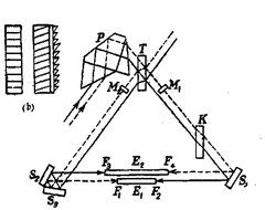
This compact instrument is used for absolute comparative measurement of slip gauges. With it, the absolute length of a slip gauge can be determined by three different methods : (1) By comparison with a standard block. (2) By a combined measurement of three gauge blocks. (3) By measurement with a wrung-on gauges block. The Zeiss optical system, which employs three wavelengths of cadmium light is illustrated in Fig. 10.15 (a) which shows the set-up for the differential method of measurement. The light of

Fig. 10.15. Zeiss slip gauge interferometer.
cadmium lamp falls on prim P and is made parallel by a lens. This light is divided by the dividing plate T. One part penetrates the compensation plate K (compensating for the path of light) and this part from plate T is deflected by mirror Si and reaches the surfaces F2 and F4 of the gauge blocks. From there it is reflected and returns to T in the same way. The other part of the light deflected from the dividing plate falls on the surfaces Fi and F3 of the gauge blocks by way of the angle mirrors S2 and S3, and is then reflected back to T. Both parts coincide behind the dividing plate, that is to say those reflected by Fi and Ft and those reflected by F2 and F3. Interference bands on the surfaces of the slip gauges can be observed by means of a second lens. By tilting one of the slip gauge tables, they are then adjusted to the position shown in Fig. 10.15 (b). As one band system originates from the superimposition of the rays reflected from Fj and F4 and the other system from F2 and F3 the displacement of the two band system is a measure of the different between the gauge blocks. This displacement for all three bands is then measured by means of the measuring device. The measured bands of both systems are brought to coincidence and the fractions are read off directly from the scale. The corresponding linear measurement in microns is then determined by means of a special slide rule.
