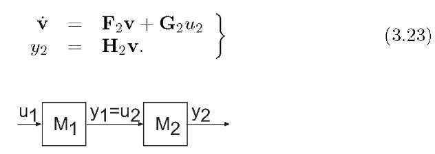
In navigation applications, it will often be the case that we have multiple interconnected systems, each of which is modeled by a set of state space equations. For design and analysis, we want to develop a single state space model for the overall interconnected system. This is achieved by the process of state augmentation. This section first describes the state augmentation process for two systems interconnected in the series configuration of Figure 3.2. From that discussion, the process should become clear and the reader should be able to extend the method to a larger number of systems interconnected in more general ways (e.g., parallel, feedback).
In Figure 3.2, the first system is represented as Mi and the second system as M2. Let the first system have the state space model
and the second system have the state space model
Figure 3.2: Series interconnection of two state space systems.
By their interconnection,![]() Therefore, if we define the augmented state vector
Therefore, if we define the augmented state vector![]() then the state space model for z is
then the state space model for z is
Other interconnections, such as parallel or feedback, yield different resulting state space formulae.
Example 3.7 Let the dynamics for v be defined by eqns. (3.16-3.17). Let the applied force be defined by
Note that this is a feedback interconnection. Define the augmented state as ![]() and the output as p. Then the augmented state model is
and the output as p. Then the augmented state model is
The state space augmentation technique will be frequently used in navigation system error analysis. The linearized navigation system error dynamics will first be derived. Then error models for the navigation instruments will be obtained either from the manufacturer or through experimentation. Finally, these state space equations will be combined through state space augmentation.
When using the state space augmentation procedure, it is critical that the analyst ensure that neither of the systems being combined loads the other system. One system loading another means that the interconnected system behaves significantly different after the interconnection than before. Typically, in navigation systems the augmented state corresponds to instrumentation error variables such as biases and scale factors. By the design of the navigation system and the instruments, the interconnection of the instruments to the navigation system does not change the performance of the instruments; therefore, the state augmentation process works successfully.
Example 3.8 The left portion of Figure 3.3 shows an example physical system where state augmentation does not lead to a valid system model.
Figure 3.3: Figure for Example 3.8. The sub-circuits are being connected at the nodes as indicated by the adjacent the black dots. Left – Example physical system where the state augmentation process would result in an incorrect model due to loading effects.
The state space models for the two disconnected systems are
where![]() Direct application of eqns. (3.24 3.25) results in the system model
Direct application of eqns. (3.24 3.25) results in the system model
which does not apply to the circuit on the left, but does apply to the circuit on the right. In the circuit on the right, an isolation amplifier is inserted at the output of the first circuit. The isolation amplifier has unity gain ![]() with high input resistance
with high input resistance![]() and low output impedance which prevents the inductive load from affecting the performance of the capacitive supply.
and low output impedance which prevents the inductive load from affecting the performance of the capacitive supply.
The correct model for the circuit on the left is 
due to the constraint that![]() The system with the isolation amplifier described in eqn. (3.28) has two real poles. The system without the isolation amplifier described in eqn. (3.29) has two complex poles.
The system with the isolation amplifier described in eqn. (3.28) has two real poles. The system without the isolation amplifier described in eqn. (3.29) has two complex poles.


