Abstract
The foundational ideas of thermodynamics, especially the implications of its two main laws, are presented, and their implications for energy engineering are discussed. Special attention is given to the implications of the second law in the design of processes that are thermodynamically efficient. The application of thermodynamics to practical engineering problems requires accurate estimation of thermodynamic properties of fluids. A survey of the methods used for such estimations is also presented.
NOMENCLATURE
All thermodynamic properties have the units of energy or energy per unit time except where otherwise specified. Cp Heat capacity at constant pressure (energy/temperature) eCh Chemical exergy ePh Physical exergy G Gibbs free energy, or Gibbs function H Enthalpy
M General thermodynamic property Mt Partial molal property of specie “i” n total number of moles nt number of moles of specie “i” P Pressure (force/area) PY Vapor pressure (force/area)
Q Heat or heat flux added to a process (energy or energy per unit time) 6ideai Heat or heat flux added to a completely reversible process (energy or energy per unit time) R Universal gas constant (energy/temperature) S Entropy (energy/temperature) T Temperature
T0 Reference temperature or temperature of the surroundings U Internal energy V Volume (length3)
W Work or power produced by a process. Usually does not include work done by or on fluids entering or leaving the process (energy or energy per unit time) Wideal Work or power produced by a perfectly reversible process (energy or energy per unit time) Wlost Lost work or power (energy or energy per unit time) Wtotal Total work or power produced by the process (energy or energy per unit time) xt mole fraction of specie “i”
x vector containing all mole fractions yH2O Mole fraction of water vapor in a vapor phase Z Compressibility factor
A Difference in the value between two states or differences between the properties of outlet and input streams AHf Enthalpy of formation ASf Entropy of formation (energy/temperature)
Subscripts f Formation o Base or reference state C Cold sink H Hot source rev Reversible
Superscripts
* Ideal gas or ideal gas state id Ideal solution
INTRODUCTION
Thermodynamics is concerned with the interaction between matter and energy on a macroscopic level. It is therefore the basic science that underlies the engineering of the use of energy in all its forms. It is governed by two basic laws with far-reaching implications. The first concerns the conservation of energy, and the second puts limits on the amount of energy that can be converted into work over and above what the first law might be thought to imply.
The actual performance of practical process equipment can be predicted by application of these two laws. That, in turn, depends on the ability to estimate the thermodynamic properties of the streams that enter and leave this equipment. The exact equations needed to calculate these properties can be derived from the formalism of thermodynamics. Certain simplifications, such as the ideal gas law or the assumption of an equation of state, are usually required to make numerical estimates of these properties.
THE FIRST LAW OF THERMODYNAMICS
Formulation
The first law of thermodynamics is a statement of the principle of conservation of energy for a closed system— namely, one in which there is no transfer of mass across the system boundaries.
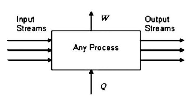
This equation ignores certain effects such as differences in fluid velocities, which become important only at very high velocities, and differences in fluid elevations, which become important only when there are greatly varying elevations. U is a thermodynamic property called internal energy. It accounts for energy due to the motion of molecules in a fluid and the exchanges of energy between them. The As refer to differences in the property value between the final and initial states of the system. U, Q, and W all have units of energy. However, this equation can also have another interpretation for open flow systems at steady state. Such systems have input and outlet streams, and possibly an exchange of heat or work with the surroundings (Fig. 1). However, the stream flows and property values throughout the system are all considered constant over time. In this case, the first law is a rate equation. A U is the difference between the sum of U times the mass flow rate for all the output streams minus that same sum for all the inlet streams. Q and W are rates of energy transfer. The arrows in Fig. 1 indicate the direction of the flow of work, W, and heat, Q, when these quantities are positive.
When applying Eq. 1 to a flow process, Wtotai includes the work done in moving fluids into and out of the process. To eliminate these effects, another thermodynamic property, namely enthalpy, H, is defined,
Fig. 1 Schematic representation of any thermodynamic process.
H = U + PV (2)
where P is pressure and V is volume.
For a flow process at steady state, this changes the first law to
AH = Q – W (3)
In Eq. 3, W is the work produced by the process apart from that involved in moving fluids into and out of the process. It is often called the shaft work.
In these equations, it is important to make a distinction between intrinsic and extrinsic properties. The former are properties per unit mass or per mole, whereas the latter are total values of the property for the mass flow of the given process stream. These and other thermodynamic relationships can be applied to either, provided that they are applied consistently.
U, H, P, and V are examples of thermodynamic state functions—that is, their intrinsic values depend only on the state of the fluid (usually its temperature, pressure, and composition) and not on the process used to bring the fluid to that state. On the other hand, quantities like Q and W are not state functions. When a fluid makes a transition from one state to another, the values of Q and W associated with that transition are dependent on the “path” over which that transition was made.
Enthalpies of Formation and Reaction
Enthalpy cannot be calculated in an absolute sense. It requires the definition of a reference state, at which it is taken to be zero. Enthalpies in all other states are referenced to this state. The most rigorous definition of a reference state is to take it as comprising the constituent atomic species in their normal molecular configurations at some temperature and pressure—typically 25°C and 1 atm. Normal molecular configuration means the normal configuration the atomic molecules take in nature, such as O2, H2, N2, etc. Thus, these molecules would be taken to have zero enthalpy at 25°C and 1 atm. The phases of these elemental species also have to be stated. They are generally taken to be the normal phase of the element at the stated conditions. The reference states for gases are usually taken to be in their “ideal gas state” (ig).[1]
With these ideas as a starting point, the enthalpies of compounds can be built up by considering real or imaginary reactions through which they are formed from their constituent elements. For example, the enthalpy of formation of methane would be the enthalpy change associated with the following reaction:
where s indicates solid and ig indicates the ideal gas state. Such chemical reactions are usually accompanied by the absorption or release of a certain amount of heat. If the reaction is carried out at constant temperature and pressure, and if no work is done, according to the first law, this heat is the enthalpy difference of the reaction and defines the standard enthalpy (or heat) of formation of the resulting compound.
| Table 1 Enthalpies of formation of some | common compounds | ||||
| Chemical specie | Formula | State | MW | AHt( T= 298.15° C) | AHf (non dim.) |
| Methane | ch4 | IG | 16.04 | - 74.87 | - 32.968 |
| Ethane | c2h6 | IG | 30.08 | - 83.8 | - 36.901 |
| Propane | c3h8 | IG | 44.10 | -104.7 | - 46.104 |
| n-Octane | cgh18 | IG | 114.23 | - 208.4 | - 91.767 |
| n-Octane | L | 114.23 | - 250.3 | -110.217 | |
| Carbon dioxide | CO2 | IG | 44.01 | - 393.51 | -173.278 |
| Carbon monoxide | CO | IG | 28.01 | -110.53 | - 48.671 |
| Water | h2o | IG | 18.02 | - 241.826 | -106.486 |
| Water | h2o | L | 18.02 | - 285.830 | -125.863 |
Units of AHi=kJ/gmole; Non-dimensionalization, AHf/RT0 where T0 = 273.15 °K.
Units of AHi=kJ/gmole; Non-dimensionalization, AHf/RT0 where T0 = 273.15 °K.
Standard enthalpies of formation are widely tabulated. An excellent source is the collection by the National Institute of Standards and Technology (NIST).[2] Enthalpies of formation for some common species are given in Table 1. They are given both in the units that appear in the NIST collection and in nondimensionalized form. The latter permits their use in any system of units simply by multiplying by RT0 in the desired units. T0 is taken to be 0°C ( = 273.15 °K = 459.67 °R), and R is the Universal Gas Constant. Note that °R represents degrees Rankine and °K represents degrees Kelvin.
Many different units are used in energy calculations. The values of some useful conversion factors and the values of the universal gas constant appear in Table 2.
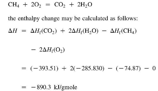
These enthalpies of formation can be combined to produce enthalpy changes for any chemical reaction whose species have known enthalpies of formation. For example, in the combustion reaction
If AH is positive, the reaction is called endothermic, whereas if it is negative, it is called exothermic. Because this particular reaction is a combustion reaction, the absolute value of its enthalpy change is also called the enthalpy change (or heat) of combustion.
Application to Combustion
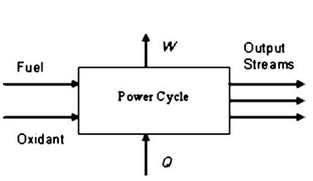
The goal of a power cycle is to convert the chemical energy of a fuel into usable mechanical energy that can produce useful shaft work or drive a generator to produce electricity (Fig. 2). What one hopes to do is to convert as much of the fuel’s chemical energy into useful work. The hope for this ideal is reflected in what is called the heating value of the fuel. It is taken to be the negative of the enthalpy change of the combustion reaction through which a fuel is completely oxidized at the so-called ISO (International Organization for Standardization) conditions—namely, 15°C and 1 atm pressure.[3] Thus, it is the negative of the enthalpy change of the following kind of reaction:
Fuel + a02 (ig) -»• bCO2(ig) + cH20(ig or 1) + Any other products( 15°C, 1 atm)
where a, b, and c are coefficients that depend on the particular fuel.
It is unfortunate that ISO conditions differ from the reference state at which enthalpies of formation are usually tabulated. Nevertheless, the latter can be adjusted to ISO conditions, and values for some common fuels appear in Table 3.
Heating Values, Heat Rates, and Power Cycle Efficiency
One area of confusion about heating values comes because of the choice of the phase of the water produced as a combustion product. If the product water is considered to be a liquid, its enthalpy will be lower than that if it is considered to be a vapor. The former choice leads to a higher heating value (HHV), whereas the latter leads to a lower heating value (LHV). If the chemical composition of the fuel is known, the heating value is the mole fraction average of the heating values of the individual constituents divided by the average molecular weight of the fuel. Where the composition of the fuel is not known, accurate heating values are determined experimentally.
Table 2 Some useful conversion factors and constants
| Type | Value | Conversion |
| Length | 1 m | 3.28084 ft 39.3701 in. |
| Mass | 1kg | 2.20462 lbm |
| Force | 1 N | 1 kg m/s2 0.224809 lbf |
| Pressure | 1 bar | 10s N/m2 10s Pa
0.986923 atm 14.5038 psia |
| Pressure | 1 atm | 14.6960 psia |
| Volume | 1m3 | 35.3147 ft3 |
| Density | 1 g/cm3 | 62.4278 lbm/ft3 |
| Energy | 1 J | 1 Nm 1 m3 Pa 10″5 m3 bar 10″3 kW s 9.86923 cm3 atm 0.239006 cal 5.12197X 10″3 ft3 psia 0.737562 ft lbf 9.47831 X10″4 Btu |
| Power | 1 kW | 103 J/s
239.006 cal/s 737.562 ft lbf/s 0.94783 Btu/s 1.34102 hp |
Values of the universal gas constant, R 8.314 J/gmole K = 8.314 m3 Pa/(gmol K) = 83.14 cm3 bar/ (gmole K) 82.06 cm3 atm/(gmole K) 1.987 cal/(gmole K)= 1.986 Btu/(lbmole R) 0.7302 ft3 atm/(lbmole R) = 10.73 ft3 psia/(lbmole R) 1545 ft lbf/(lbmole R)
Fig. 2 Schematic representation of a power cycle.
The heat rate is one often-tabulated measure that is used to describe the effectiveness of a machine—such as an internal combustion engine or a gas turbine—used to convert the chemical energy of a fuel into usable mechanical or electrical energy. Several definitions go into it.
Heat Energy Input(Btu/s)
= First Law Available Chemical Energy
= Heating Value of a Fuel (Btu/lb)
X Fuel flow rate (lb/s) Heat Rate(Btu/kWh)
= Heat Energy Input (Btu/s)
X 3600 (s/h) / Power Produced (kW)
The heat rate is based on a particular choice of either HHV or LHV of the fuel. The higher the heat rate, the more fuel is being used per kW of power produced and therefore the less efficient the machine. The heat rate is directly related to the efficiency.
Efficiency
Comparison with the previous equations yields Efficiency
= Conversion Factor (Btu/kWh)/Heat Rate (Btu/kWh)
The conversion factor’s role is strictly to convert the units. In the units shown it is equal to Conversion Factor
= 9.47831 X 10″4 Btu/J X 1000 J/kW-s
X 3600 s/h = 3412.19 Btu/kWh
Table 3 Heating values of some common fuels
| Fuel | Btu/lbm | HHV
Btu/gal |
Btu/lbm | LHV
Btu/gal |
LHV/HHV |
| No. 2 oil | 19,580 | 142,031 | 18,421 | 133,623 | 0.9408 |
| No. 4 oil | 18,890 | 146,476 | 17,804 | 138,055 | 0.9425 |
| No. 6 oil | 18,270 | 150,808 | 17,312 | 142,901 | 0.9476 |
| Diesel fuel | 19,733 | 18,487 | 0.9368 | ||
| Hydrogen | 61,007 | 51,635 | 0.8464 | ||
| Methane | 23,876 | 21,518 | 0.9012 | ||
| Typical natural gas | 22,615 | 20,450 | 0.9019 | ||
| Propane | 21,653 | 19,922 | 0.9201 | ||
| Butane | 21,266 | 19,623 | 0.9227 | ||
| Gasoline | 19,657 | 121,808 | 18,434 | 114,235 | 0.9379 |
| Reformulated | 19,545 | 120,103 | 18,304 | 112,377 | 0.9365 |
| gasoline | |||||
| Methanol | 11,274 | 73,882 | 10,115 | 66,289 | 0.8972 |
| Anthracite coal | 14,661 | 14,317 | 0.9765 | ||
| Bituminous coal | 14,100 | 13,600 | 0.9645 |
When the power-generating equipment is used to produce electricity, the efficiency is often called the electrical efficiency.
The efficiency calculated by the above equations is based on the hope of converting the entire heating value of the fuel into useful work. It is unfortunate that this has come to be the standard because there is a further limitation imposed by the second law of thermodynamics. It tells us that nature will not allow conversion of this much chemical energy into useful work, even if the power cycle were constructed as perfectly as possible under the most ideal conditions.
THE SECOND LAW OF THERMODYNAMICS
Reversibility
Before stating the second law specifically, it is necessary to introduce the concept of reversibility. Most processes produce changes in the substances on which they operate. Reversibility has to do with how easy it would be to undo the changes that are produced in a substance through some process. Specifically, reversibility means that a change that a process makes on a substance could theoretically be undone (reversed) with only an infinitesimal change in the conditions in the process.
For example, suppose that heat is exchanged by allowing heat to flow from a hotter substance to a cooler one. For this change to be reversible, temperatures at every point where heat transfer takes place must differ only infinitesimally. Thus, if we raised the temperature profile of the cooler substance by just an infinitesimal amount, the heat could be transferred back to the hotter substance.
As another example, suppose that a gas is compressed in a cylinder by moving a piston in such a way that it reduces its volume. For the change to be reversible, the pressure the piston exerts must be only differentially greater than the pressure of the gas. In this case, if the piston pressure were reduced only infinitesimally, the gas could be expanded back to its original state, and all the work of compression would be recovered. On the other hand, if a pressure were applied that differed substantially from that of the gas in the piston, the change brought about would be irreversible, because a differential change in the applied pressure could not reverse the effects of the compression.
Formulation
The second law of thermodynamics has a certain mystique to it because unlike most physical laws, it is not a conservation law (e.g., conservation of mass, energy, momentum, etc.). Instead, it puts certain limits on what nature allows in spite of the great conservation laws. It is also not as intuitive as the other great laws. Therefore, much has been written to try to explain it. However, it can be applied rigorously based on the following three-part formulation. This formulation refers to a given substance of constant mass that experiences changes from an initial to a final state through the possible exchange of heat and work with its surroundings.
Part 1: There is a thermodynamic state function, called entropy, S, which is defined by the following equation:
where dS is the differential change in entropy and dQrev refers to a differential amount of heat transferred to or from a substance in a reversible manner. That is, to calculate finite entropy differences, this equation needs to be integrated along a reversible path.
Stating that entropy is a state function is not a trivial claim. What it means is that no matter what reversible path is chosen, the net change in entropy will be the same, provided that the initial and final states are the same.
Part 2: No matter how a change of state is brought about in a given substance,
The differences implied by the As are differences between the end state and the initial state of both the substance and surroundings. Notice that there is such a thing as a change in the entropy of the surroundings as well as the substance. It too can be calculated by Eq. 4.
Part 3: The inequality in the previous equation becomes an equality if, and only if, the process used to bring about the change is completely internally reversible and if the process also exchanges heat with the surroundings in a completely reversible manner.
Thus, this third part becomes a criterion of reversibility for a process or piece of equipment. Furthermore, the greater the inequality, the greater the irreversibility.
In general, the surroundings are considered to be at a constant ambient temperature, T0. Thus,
where the two Qs are heat transfers to the surroundings and substance, respectively, which are the same in magnitude but opposite in sign. This equation can be combined with Eq. 5 to give
Along with the first law for flow processes, this gives
In these equations, the subscripts have been dropped and all quantities refer to the substance, not the surroundings. Furthermore, although these equations were derived for changes in a substance of constant mass (closed system), as with the first law, they can also be applied to a steady flow system. In this case, the As refer to differences in the fluxes of the thermodynamic properties between the output and inlet streams.
The implications of these two equations are very significant. They mean that in a flow process, if the inlet and outlet conditions of the various streams are fixed, there are an upper bound to the amount of heat that can be transferred to the process and an upper bound on the amount of work it can produce. The latter claim has an impact on power generation systems because it imposes a limit on the amount of power that can be produced from a given amount of fuel, regardless of its energy content. Furthermore, because the entropy change of such processes is usually negative, another implication of Eq. 7 is that a certain amount of heat must be rejected to the surroundings regardless of how well the process is designed internally.
The Carnot Engine
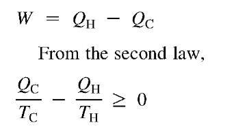
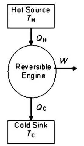
Some of the implications of the second law can be illustrated through the so-called Carnot engine. This is an imaginary reversible engine in which heat, QH, is transferred from a high-temperature source at TH into a reversible engine, which produces work, W, and discards heat, Qc, into a cold sink—possibly the environment—at 7c (Fig. 3). From the first law,
If the Carnot efficiency is defined as the amount of work that can be produced from the high-temperature heat (i.e., WIQu),
The last term on the right is of particular interest. It means that the Carnot efficiency depends on only the temperatures of the two heat reservoirs. All the heat in a high-temperature source can never be converted to work, even if the apparatus is perfectly reversible. The higher the temperature of the hot source relative to the cold sink, the higher the Carnot efficiency.
Fig. 3 The Carnot engine.
Ideal Work, Lost Work
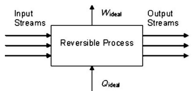
The second law gives a means to measure the irreversibility of a process or piece of equipment. That, in turn, is a measure of its departure from an ideal design—one which makes changes to substances in a way that most preserves their work-producing potential. This analysis begins by imagining a perfectly reversible process and defining Wideai and Qideal to be the limiting values defined by Eqs. 7 and 8 (see Fig. 4).
These ideal values can be determined from the enthalpies and entropies of the various streams entering and leaving the process alone, without reference to any of the internal details of the process.
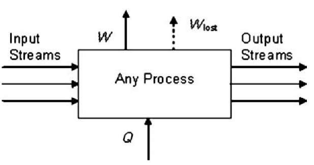
The level of irreversibility in a real process or in some part of it can be quantified through what is called lost work.[7] Because the actual work that can be obtained from any real process is always less than that what would have resulted from a completely reversible process, this leads to the following definition:
A real process—or any subprocess—can be represented as shown in Fig. 5. The Wlost stream is not an actual work output. However, showing it in this manner is a reminder that in any real process a certain amount of the potential to do work has been lost due to the irreversibilities of the process. Furthermore, the lost work of all the subprocesses within the overall process sum up to the lost work of the process as a whole,
Fig. 4 Schematic representation of a reversible thermodynamic process.
where the summation is carried out over each of the subprocesses. When analyzing a process, Eq. 13 can be applied to each piece of equipment. Then the Wlost for each of these can be summed according to Eq. 14. Such an analysis brings out where the greatest irreversibilities occur and therefore shows where the greatest opportunities are for improvement.
Exergy
Lost work is related to the modern concept of exergy. Lost work gives a quantitative measure of the irreversibility of a process or subprocesses within it. Furthermore, the term “lost work” seems quite descriptive. However, it is also possible to assign values—perhaps even monetary values—to streams as well as equipment. This can be done through the concept of exergy.
The exergy of a stream is the maximum amount of work that could theoretically be extracted from that stream if its temperature and pressure were reduced to that of the environment and if the concentrations of its chemical species were brought to that of the environment. It should be clear that from a power-production point of view, the economic value of a stream is related to its exergy because the production of work is usually more valuable than the production of heat alone.
Exergy analysis is based on the idea that it costs something in terms of equipment, power, adding costly streams, etc. to raise a stream’s exergy—and hence its value. If what it costs to raise the value of a given stream is less than the increased value of the stream, it is a desirable thing to do.
Exergy is generally divided into four parts: physical, chemical, kinetic (having to do with the velocity of the fluid), and potential (having to do with its height above some datum level). The first two of these parts are of primary interest here. Physical exergy is the negative of the ideal amount of work that could be extracted from a stream if its temperature and pressure were reduced to ambient conditions. That is,
Fig. 5 Schematic representation of any process showing lost work.
In Eq. 15 and the following equations, the As refer to differences between the present state of the fluid and its state at ambient conditions.
Chemical exergy, <?Ch, also has to be added because the exergy, say, of a fuel at ambient conditions ought to be higher than that of its eventual combustion products at those conditions because it has the potential of producing work in being transformed into its products. This can be accounted for in an equation similar to the one above, but this time involving properties of formation at ambient conditions.
Exergy is not quite a thermodynamic state function because it depends on environmental temperature. Also, unlike enthalpy or internal energy, it is not conserved in a process. Nevertheless, it is a useful measure of the power-producing value of a process stream. In any real processes, every process step results in a net loss of exergy.
The relationship between exergy and lost work is very straightforward—namely,
where the summations are carried out over all incoming and outgoing streams, respectively.
Reversibility Revisited
The preceding analysis shows how the second law can be used to provide a measure of the irreversibility of a process or part of a process. Every irreversibility causes a loss in the potential to convert energy into work. In this era of diminishing supplies of cheap fuels and increasing demands for electric power, this is an important consideration. Furthermore, irrersibilities in one part of a process reduce the amount of work that can be produced—or else increase the amount of work that is needed—in the rest of the process, even though the source of the irreversibility may be far removed from the place in the process where work is produced or consumed.
The following is a list of some process steps that introduce irreversibility into processes, including power cycles:
• Heat transfer across a nonzero temperature difference
• Mixing of fluids of differing pressures, temperatures, or compositions
• Pressure drops that do not recover work
• Chemical reactions that do not take place at equilibrium conditions
• Flashing of liquids when pressure is reduced
• Two-phase contact and mass transfer between fluids whose various species have concentrations that differ from their equilibrium values
• Temperature and pressure shocks when fluids enter equipment at different temperatures or pressures from those that are present within the equipment
The most thermodynamically efficient designs—those that most preserve the work-producing potential of the fluids in the process—are those that strive for the greatest reversibilities in the various pieces of process equipment. However, there is another side to this question. The more reversible a piece of equipment is, the greater its capital cost is apt to be. Thus, in the practical design of equipment there is often a trade-off between reversibility and capital cost. Processes need to be evaluated not only for their thermodynamic efficiency, but also for their thermoeco-nomic effectiveness.
CALCULATION OF THERMODYNAMIC PROPERTIES
The Rigorous Equations
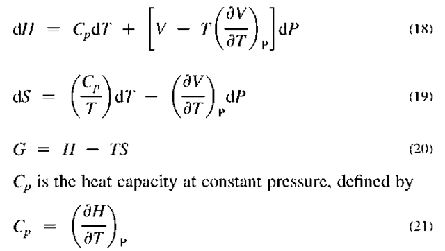
Process equipment cannot be designed or evaluated apart from the ability to estimate the thermodynamic properties of the entering and exiting streams. The following are rigorous equations for the calculation of some of the important thermodynamic properties of pure or constant-composition substances[8]:
G is called the Gibbs free energy or Gibbs function and has importance in equilibrium calculations. Eq. 20 can be considered its definition. By differentiation and comparison with the other two, it can be shown that
These are differential equations that emphasize that these properties need reference values from which differences can be calculated. To obtain values for the property differences for real substances, the pressure-volume-temperature (PVT) behavior of the fluid needs to be inserted into the equations, which would then be integrated to produce the final results.
The Ideal Gas
One way of inserting PVT behavior is through equations of state. One of the simplest models for gases is that of the ideal gas, whose equation of state on a molar basis is:
PV = RT (23)
This equation reflects the fact that the molecules in the gas do not interact in any way, although they may have very complex energy interactions within a given molecule.
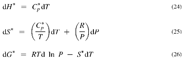
When this equation is inserted into the rigorous equations, one obtains
where the asterisk designates the properties as those of an ideal gas.
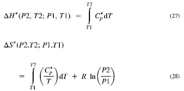
The integrated forms of Eqs. 24 and 25 are
The heat capacity has been left behind the integral sign because even for most ideal gases, it varies with temperature. However, neither ideal gas heat capacities nor enthalpies vary with pressure, but ideal gas entropies do. Ideal gas heat capacity data is often presented in the form of an analytical equation. One common form used by NIST[9] is
NIST tabulates the constants (A, B, etc.) for many compounds.
Real Fluids
Real fluids may be represented by the following general equation of state:
where Z is the compressibility factor, which can be a function of both P and T. It is common to report PVT data in the form of the compressibility factor. For an ideal gas, Z = 1. Thus, the compressibility factor is a measure of the deviation from ideal gas behavior.
When Eq. 30 is substituted in Eqs. 18 and 19, one obtains
One consequence of these equations is that thermo-dynamic properties of real fluids can be calculated from their ideal gas-heat capacity (as a function of temperature) and their PVT behavior. This follows from the fact that to get from one state to another, these equations can first be integrated to zero pressure (which requires only PVT data), then integrated at zero pressure to the final temperature (which requires only ideal gas heat capacity data), and then integrated back to the end-point pressure.
Several approaches have been used to apply these equations for practical calculations. A first approach is to take known ideal gas-heat capacity and PVT data, and use them directly in these equations. Such data are not often available, and even when they are, this is a tedious process. Nevertheless, it has been done for a number of well-studied chemical species, most notably water. This is the basis of the steam tables, which have been put into analytical form for easy computer calculations.[10]
A second approach is through generalized correlations. An early attempt to describe the PVT behavior of many fluids was begun by Pitzer[11] through the use of his so-called acentric factor. His correlations have been extended so that they can be used to predict the more important thermodynamic properties of real no-polar fluids in both vapor and liquid phases.[12]
A third approach is to insert an equation of state into Eqs. 31 and 32 so that they may be integrated analytically. One excellent equation of state for low-density gases is the virial equation
where B, C, D, etc. are functions of temperature only and are called the second, third, fourth, etc. virial coefficients. There is a great deal of data for the second virial coefficients.1-13-1 Where data are not available, correlations have been developed to estimate them.[14,15] Third virial coefficients are usually not available, but prediction methods have been proposed.[16] Very little information is available for higher-order coefficients. Other equations of state have also enjoyed success in predicting properties of real fluids, both in the vapor and liquid phases. Among the more successful are the Soave-Redlich-Kwong[17] and Peng-Robinson[18] equations.
Solutions
The properties of solutions—whether they are gas or liquid mixtures—are not merely the mole fraction averages of the properties of the pure components. For any thermodynamic property, M, the exact equation for the properties of mixtures is
where M, is called the “partial molal property of i” and x is a vector containing all of the compositions of the various constituents of the solution. The summation is carried out over all constituents. M, is the property of constituent i at pressure, P, and temperature, T, as it exists in solution of composition x. In general, this is different from its value as a pure substance.
The most general equation through which partial molal properties may be evaluated is
where n is the total number of moles and n, is the number of moles of specie “i”.
The partial derivative implies that the extensive property, nM, is differentiated with respect to the particular specie of interest, i, with pressure, temperature, and all of the other constituent amounts held constant. If properties of the various possible mixtures are known or can be approximated analytically, this equation provides a means to calculate their partial molal properties.
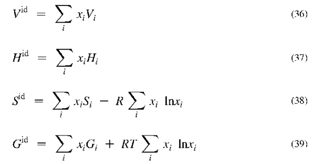
An important approximation for solutions is that of so-called “ideal solutions,” whose properties are calculated as follows,
where the superscript, “id,” designates these as the properties for ideal solutions. All ideal gases are ideal solutions. The ideal-solution approximation is useful in some situations, but most liquids depart from it significantly. Notice also that properties involving entropy have a mixing effect (second terms on the right side of Eqs. 38 and 39) even if they are ideal solutions. This reflects the fact that the entropy of a solution is always higher than the combined entropies of its constituents.
The true properties of solutions can be calculated from their PVT behavior. For humid air, for example, the mixing effect is often neglected. However, one recent study done by M. Conde Company[19] includes virial coefficient information, including information for mixtures, sufficient to produce very accurate psychrometric properties of air-water mixtures.
Phase Equilibrium
Phase equilibrium can also be predicted from thermo-dynamic properties. The way this is done goes beyond the scope of this entry. However, several ideas can be stated here. One aspect of phase equilibria—namely pure-component vapor pressures—has been widely measured and can be used as a starting point for multicomponent phase equilibrium estimates. Vapor pressure data is often correlated by the Antoine equation,
where A, B, and C are constants. Such constants for many compounds also appear in the NIST collection.[20]
One special case of interest in energy calculations is the two-phase equilibrium between (1) pure liquid water and (2) a vapor phase one of whose components is water vapor. If the vapor phase is considered to be an ideal gas (and thus an ideal mixture), and if certain other assumptions are made, the composition of water in the vapor phase can be estimated by
where the vapor pressure can be calculated from the Antoine equation. This is a useful approximation that can be refined if PVT data for the vapor mixture are available.
CONCLUSIONS
This entry attempts to give an introduction to some of the basic principles of thermodynamics and how they relate to various energy engineering applications. The two main laws of thermodynamics govern the performance of any energy-conversion process. Their application requires the ability to estimate the thermodynamic properties of the various process streams. Such estimates are also based on the formalism that thermodynamics provides. Thus, thermodynamics provides the basic framework within which the design and evaluation of all energy-conversion equipment and processes must be performed.

