Abstract
This entry first identifies the energy conversion principles that govern reciprocating piston devices. Next, the hardware and operating cycles used in practical reciprocating piston internal combustion engines are described. Finally, current issues, trends, and analysis approaches used in developing combustion and air handling systems are discussed.
INTRODUCTION
The goal of any engine is to convert the energy contained in a fuel into useful work as efficiently and cost-effectively as possible. Engines can be classified into various families based on how this conversion is accomplished. The internal combustion engine is one such family; in this family, a combustion reaction between a fuel and oxygen occurs within a mechanical device designed to harness the energy and produce work. This discussion addresses one mechanical configuration in the family of internal combustion engines. Other mechanical configurations of practical internal combustion engines are the gas turbine and rotary (Wankel) engine.
ENERGY CONVERSION AND RECIPROCATING PISTON DEVICES
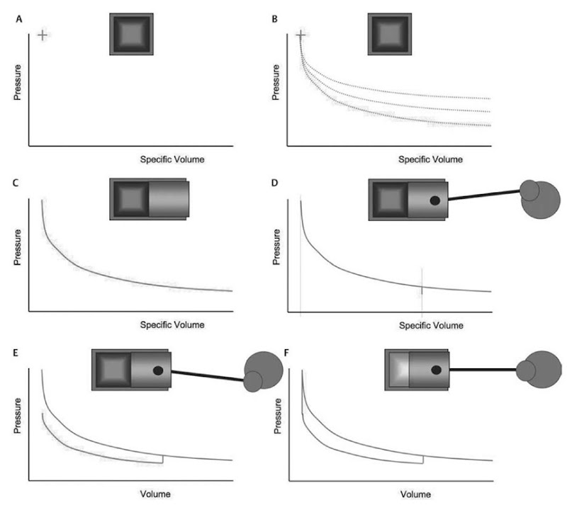
Consider a sealed chamber in which a combustion reaction has just occurred, as shown in Fig. 1A. When a fuel reacts with oxygen, the chemical energy contained in the fuel is converted to sensible energy, which is physically sensed as a temperature increase in an open flame, and if the chamber is confined as shown here, an increase in temperature and pressure. The state within the chamber after combustion is indicated on coordinates of pressure and specific volume in the figure.
One can now begin considering various approaches for energy conversion. The possibilities include:
• Heat transfer from the chamber supplying energy to another device
• Mass transfer from the chamber and flow through a turbine
• Work transfer across a moveable chamber wall
Each possible approach follows some process line, as shown in Fig. 1B, which will ultimately bring the combustion gas to equilibrium with the outside environment. At equilibrium, the gas will have the same pressure, temperature, and chemical make-up as its surroundings. Unfortunately, any practical engine will release the gas to the environment before equilibrium is completely attained.[1] In other words, the temperature, pressure, or mixture concentration will still differ from the environment, but it becomes impractical to recover any further work.
If the curves shown were extended sufficiently to the right, each of these processes would have a different temperature when reaching atmospheric pressure. If work is being produced throughout the chosen process, intuition suggests that the process with the lowest temperature when atmospheric pressure is reached will be most efficient. The ideal process would simultaneously reach both pressure and temperature equilibrium with the environment. However, according to the Second Law of Thermodynamics, such a process does not exist.[1] The very best process—the highest efficiency process—is the one in which constant entropy is maintained. The temperature of the gas when atmospheric pressure is reached is still above atmospheric temperature, but all observations have demonstrated that a more efficient process cannot be achieved.
The reciprocating piston engine is one in which work transfer occurs across a moving combustion chamber wall (piston), as depicted in Fig. 1C. The pressure in the chamber forces the piston to the right, and work is performed on the piston. An important attraction of this moving piston device is that it has been found to follow a process line very closely resembling the isentropic process.
A very important practical concern arises: expansion to atmospheric pressure requires moving far to the right on the pressure versus specific volume coordinates. Because there is no change in the gas mass, the specific volume scale can be replaced with a volume scale, and it must be concluded that expansion to atmospheric pressure requires a very long chamber.
Fig. 1 Thermodynamic idealizations of reciprocating piston engine processes.
Fortunately, the isentropic process is quite non-linear. The pressure drops rapidly and the majority of the work extraction occurs early in the process. For practicality in regard to engine packaging, piston movement is stopped at some chosen maximum volume, and the remaining gas is expelled from the chamber.
In the arrangement shown in Fig. 1D, the piston is linked through a connecting rod to a crankshaft. This arrangement results in a defined maximum volume and the opportunity to create a repeated series of processes in which the piston is cycled between this maximum and some minimum volume. Thus, with suitable arrangements for bringing in a new mixture of fuel and oxygen and initiating combustion, work can be repeatedly produced. This arrangement also provides for convenient work extraction through the spinning crankshaft.
Fig. 1E shows a compression process. The linkage arrangement returns the piston to minimum chamber volume with a new charge in the cylinder. Work is required to compress the new charge, but here, too, the moving piston results in compression in a nearly 100% isentropic efficiency process.[1]
The cycle concludes as shown in Fig. 1F—with another combustion reaction from which the processes are repeated. This has been a conceptual discussion that demonstrates process idealizations. Much of engine development involves controlling the actual, practical processes to accomplish an engine operating cycle, and minimizing the deviations of the actual processes from the ideals. Practical processes for transferring fresh fuel and oxygen into the chamber, initiating and controlling the combustion process, and transferring the reacted gases out of the chamber are fundamental to the work of engine development.
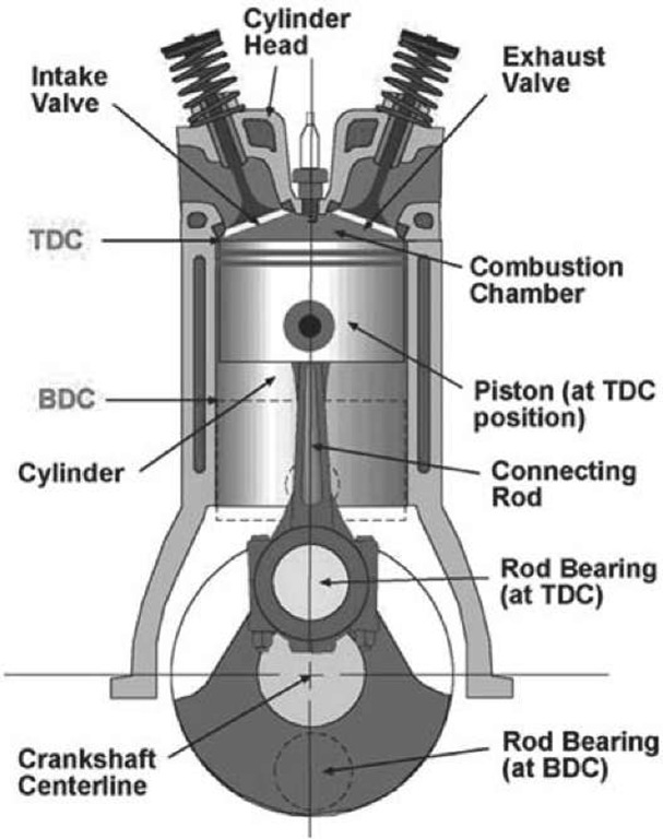
Fig. 2 Key components of reciprocating piston engines.
PRACTICAL ENGINE HARDWARE AND OPERATING CYCLES
The latter discussion identified the rationale behind the reciprocating piston engine. While many other mechanical configurations have been proposed, patented, and demonstrated over the years, few have enjoyed commercial success. Such success results from the ability to address both efficiency and cost-effectiveness.
The primary components of the reciprocating engine are shown in Fig. 2. The moving piston controls the volume of the combustion chamber between a minimum at top dead center (TDC) and a maximum at bottom dead center (BDC). The ratio between the volume at BDC and TDC is referred to as the compression ratio. The change in volume is the displacement of the cylinder, which, when multiplied by the number of cylinders, is the engine displacement.
The cylinder is sealed by the cylinder head opposite the moving piston. In most engines, the intake and exhaust valves are located in the cylinder head, as shown. The piston is linked to the crankshaft through a connecting rod. As the crankshaft spins about its centerline (the main bearing bore in the cylinder block), the offset of the rod bearing from the main bearing determines piston travel. As the crankshaft rotates a half revolution from the position shown in the figure, the piston moves from its TDC to its BDC position. The distance the piston travels is the engine’s stroke, equal to twice the offset between the main bearing and rod bearing centerlines of the crankshaft. The cylinder diameter is termed its “bore”; the combination of bore and stroke determines the cylinder displacement.
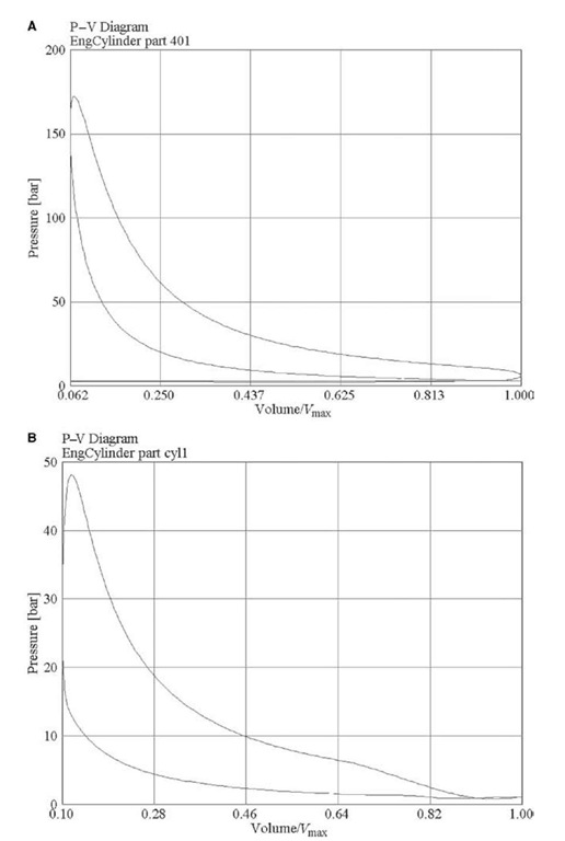
Actual engine operation, based on the idealized operating cycle, can be further explained with reference to the pressure-volume diagrams of Fig. 3. The diagram in Fig. 3A is comprised of a four-stroke engine, while the Fig. 3B diagram depicts a two-stroke engine. The four-stroke engine requires four strokes of the piston—or two revolutions of the crankshaft—for completion of each cycle. The additional revolution is used to exhaust spent combustion products on the upward stroke of the piston, and draw in fresh reactants on the downward stroke. These additional strokes result in the relatively low pressure “pumping” loop at the base of Fig. 3A. The four strokes can be summarized as follows:
• Intake—the piston moves from TDC to BDC with the intake valve open, drawing fresh reactants into the cylinder.
• Compression—the valves are closed and the piston moves from BDC to TDC, compressing the reactants. The combustion reaction is initiated as the piston approaches TDC, increasing the pressure and temperature in the sealed chamber.
• Expansion—the high pressure forces the piston from TDC to BDC, transferring work to the crankshaft.
• Exhaust—the exhaust valve opens and the piston moves from BDC to TDC, forcing the spent exhaust products out of the chamber.
In the two-stroke engine, the operating cycle is completed in a single crankshaft revolution. Gas exchange is completed as the piston approaches BDC. Intake and exhaust passages are simultaneously opened, and a pressurized intake system is used to force the exhaust products out and fill the cylinder with a fresh charge in this scavenging process. The scavenging process results in the small process loop at the right of Fig. 3B (near BDC volume).
Today, considerable effort is devoted to gas exchange or “breathing” processes in engine development. Design goals include minimizing flow restrictions, maximizing spent products removal, and maximizing cylinder-filling with fresh reactants. Note that conventional spark-ignited gasoline engines operate with a premixed, nearly homogeneous fuel-air mixture. Load is controlled by throttling because of the relatively narrow ignitability limits of gasoline-air-residual mixtures, and this incurs substantial pumping losses at part load.
Another important aspect of engine development pertains to the combustion process. The idealization of Fig. 1F assumes an instantaneous combustion reaction, while the piston is at TDC. While this would result in maximum efficiency, real combustion processes are rapid, but not instantaneous. This fact, and the need to manage the peak pressure seen by the engine’s structure, result in combustion processes that are initiated slightly before TDC as the piston nears the end of the compression stroke.
Fig. 3 (A) Four-stroke diesel pressure-volume diagram at full load. (B) Two-stroke spark-ignition pressure-volume diagram at full load.
Two approaches are prevalent in production engines. In a conventional spark-ignition engine, a mixture of air (the oxygen carrier) and fuel are drawn into the combustion chamber during the intake process. The mixture is compressed, and combustion is then initiated using a high-energy electrical spark. In the compression-ignition (diesel) engine, air alone is drawn into the cylinder and compressed. Fuel is injected directly into the cylinder near the end of the compression process. The fuel used in the compression-ignition engine is intended to easily spontaneously ignite when exposed to the temperature and pressure of the compressed air. While the diesel engine is often portrayed as having a slower combustion process (constant pressure instead of constant volume in the idealization of Fig. 1F), the goal of rapid combustion near TDC for maximum efficiency applies to both diesel and spark-ignition engines.
In order to increase the specific power output of an engine (power output per unit of displacement), some form of pre-compression (supercharging) is often considered. This is rapidly becoming standard practice in diesel engines, and is often seen in high-performance spark-ignition engines.
A crankshaft-driven compressor may be added to elevate the pressure of the air (or mixture) prior to drawing it into the cylinder. This allows more mixture to be burned in a given cylinder volume. Recognizing that the exhaust gases leaving the engine still contain a significant quantity of energy, an alternative is to use a portion of this energy to drive the compressor. This configuration is the turbocharged engine.
When air is compressed, its temperature increases. Its density can be further increased (and still more air forced into the cylinder) if it is cooled after compression. The charge air cooler, variously termed intercooler (cooling between stages of compression) and after cooler (cooling after compression) may be used with either the turbocharger or crankshaft-driven supercharger.
ENGINE ANALYSIS
The remaining sections of this entry address analysis and development of practical engines, emphasizing engine breathing and combustion process optimization to meet efficiency and exhaust emission control needs. After a century of development it might be believed that the internal combustion engine would have little potential for further improvement. Nevertheless, new emissions standards have been promulgated that require the consideration of new technologies.1-2-1 In response, engines continue to show substantial improvements in efficiency, power, and reduced emissions. Some of these advances have been due to the use of detailed analysis tools. Recent advances in computer speed and model development make the use of modeling increasingly attractive for engine design. Analysis tools include zero-dimensional thermodynamic models to analyze the in-cylinder combustion heat release, one-dimensional flow models to design the air handling and fuel injection systems, and multi-dimensional models that are useful in optimizing in-cylinder combustion and engine coolant systems.[3]
Gas Exchange Process
The gas exchange process controls the power achievable from the engine.[1] A conventional premixed-charge gasoline (i.e., spark-ignition) engine’s intake system consists of the air filter, carburetor, and throttle plate or port fuel injector, intake manifold, intake port, and intake valves. Supercharging can be used to increase air mass into the cylinder in both gasoline and diesel engines. Spatial and temporal variations in flow and pressure throughout intake and exhaust manifolds must be considered to maximize cylinder filling and scavenging.
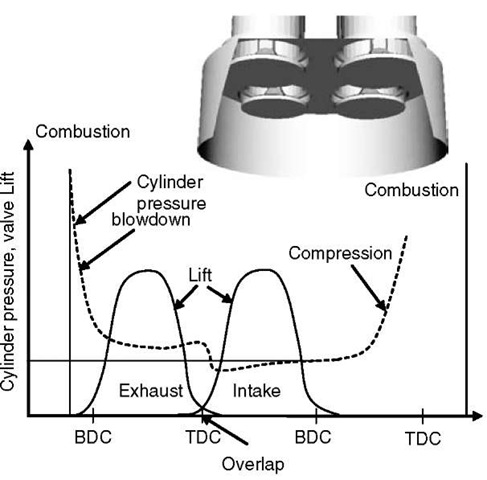
Intake system pressure drop occurs due to quasi-steady effects (flow resistances), and unsteady effects (wave action in the runners). Wave propagation is exploited in engine tuning and can be modeled effectively using commercial one-dimensional fluid flow software. Modeling is also needed to ensure equal airflows to each cylinder in a multi-cylinder engine. Engine breathing is affected by the intake and exhaust valve lifts and open areas (see Fig. 4), where much of the loss occurs, and valve overlap, which can cause exhaust gases to flow back into the intake system or intake gases to enter the exhaust (depending on the intake/exhaust pressure ratio), especially at low engine speeds.[4] At high engine speed, valve overlap can improve breathing since the inertia of the flowing gases can cause inflow into the cylinder even during the compression stroke. With Variable Valve Actuation (VVA) technologies, valve timing can be used to control the effective compression ratio (through early or late intake valve closure), or with exhaust gas re-induction (re-breathing) to control in-cylinder temperatures. Residual gas left from the previous cycle affects the engine combustion processes through its influence on charge mass, temperature, and dilution.
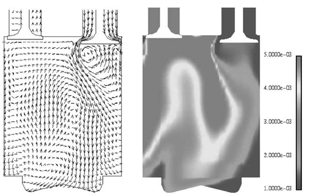
Accurate descriptions of valve flow losses require consideration of multidimensional flow separation phenomena and their effect on the conditions within the cylinder at intake valve closure.[5] A typical valve timing diagram and predictions of the in-cylinder flow during the gas exchange process for a heavy-duty diesel engine (see Table 1) are shown in Figs. 4 and 5, respectively.[6] Fig. 5 shows velocity vectors and residual gas mass distributions in the engine just as the intake valves are about to close. The highest mixing of incoming fresh charge and combustion products occurs where the intake flow velocities are the largest due to high flow turbulence.
Fig. 4 Intake and exhaust valve arrangements for diesel engine.
Table 1 Heavy-duty diesel engine specifications
| Engine details
Cylinder bore (mm) |
Caterpillar 3401
137.2 |
Cummins N14
138.3 |
| Stroke (mm) | 165.1 | 152.4 |
| Compression ratio | 16.1 | 15.1 |
| Displacement /cyl (l) | 2.44 | 2.48 |
| Fuel injection system | ||
| Injectors | 6 or 8 holes, 0.26 mm diameter | |
| Caterpillar port/ valve data | ||
| Exhaust valve | - 217° ATDC | |
| opening | ||
| Intake valve | 220° ATDC | |
| opening | ||
| Intake valve closing | -143° ATDC | |
| Intake valve diameter | 45 mm | |
| Exhaust valve diameter | 41.8 mm | |
| Maximum valve lift | 11.0 mm | |
| Intake port diameter | 40.38 mm | |
| Exhaust port diameter | 37.21 mm | |
| Port lengths | 130 mm |
DIESEL ENGINES
Improvements in diesel engine technology in the last decade have been due to factors such as the introduction of high-pressure electronic fuel injection systems and multistage turbocharging, guided by insights obtained from computer modeling. Simulating the diesel engine represents one of the most complex and comprehensive modeling problems conceivable. The Navier-Stokes equations must be solved with consideration of when moving boundaries, turbulence, heat transfer (including radiation), sprays, combustion and emissions, and commercial and open source computer codes[7] are available.
Computer models are not entirely predictive due to the wide range of length and time scales needed to describe engine fluid mechanics. For example, a modern truck diesel engine operates with injection pressures as high as 200 MPa, with injector nozzle holes less than 200 (im in diameter. Thus, the fuel jet enters the high-temperature combustion chamber gas close to sonic velocity (~ 600 m/s) and breaks up into droplets with diameters less than 10 (im in microseconds. To begin to resolve these processes in a combustion chamber of bore 100 mm, more than (104)3 = 1012 grid points would be required. Current, practical computer storage capabilities are limited to about 105 or 106 grid points. Accordingly, sub-models are used to describe unresolved processes,[8] as summarized in Table 2.
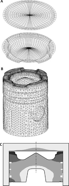
The combustion chamber surface temperature is needed to specify wall boundary conditions (see Fig. 6[19]). In the model, heat flux from the gas-side is used for the metal component heat-conduction prediction. Localized high temperature regions are predicted near the piston bowl rim in agreement with engine experimental data.
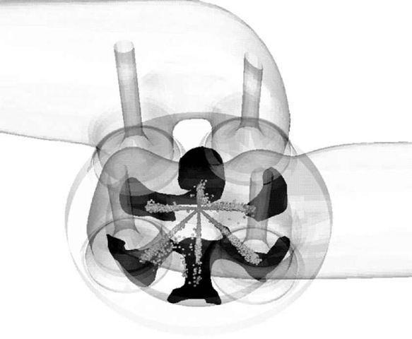
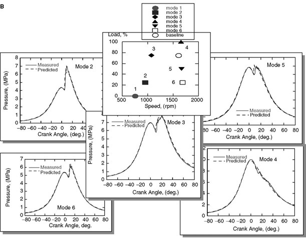
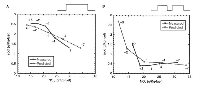
Following fuel injection and atomization, injected fuel droplets vaporize and mix with the compressed air. Auto-ignition takes place and the burning rapidly consumes the premixed mixture. Thereafter, the burning that occurs while the injection continues occurs via mixing-controlled or diffusion-type combustion. Fig. 7A shows predicted spray plumes and soot formation regions for a Caterpillar diesel engine (see Table 1). Good agreement between measured and predicted in-cylinder pressures and soot and NOx emissions are shown in Figs. 7B and 8, respectively.[5'12]
Fig. 8 also shows that staged or multiple injections are effective for emissions reduction, and the mechanism of emission reduction is summarized in Fig. 9.[20] Soot accumulates at the tip of the spray jet (see also Fig. 7A), as also confirmed experimentally in optical engines.[21] With single injection, the high-momentum injected fuel penetrates to the fuel-rich, relatively low-temperature jet tip and continuously replenishes it, producing soot. With a split-injection, the soot cloud of the first plume is not replenished with fresh fuel, but continues to oxidize.
Fig. 5 Computed flow velocities (left) and residual gas distribution (right) during gas exchange in plane of valves (144 degrees ATDC— 1600 rev/min)
GASOLINE ENGINES
Gaseous pollutant emissions (NOx, CO, and HC) from gasoline engines have been controlled effectively using the three-way catalyst. However, in order to permit both reductions of NOX and the oxidation of hydrocarbons and CO, combustion must occur at the chemically balanced (stoichiometric) air-fuel ratio within very narrow limits. Issues such as cold-start emissions, fuel economy, and engine responsiveness have been the main drivers for further advancements. The fuel system of spark-ignition engines has evolved from carburetion to throttle-body injection, followed by Port Fuel Injection (PFI), including sequential-fire injection.
Table 2 Example physical submodels used in diesel engine computer modeling
| Physical process | Submodel |
| Turbulence | RNG k-e [9] |
| Heat transfer | Log-law [9] |
| Nozzle flow | Cavitation [10] |
| Atomization | Jet instability [11] |
| Drop breakup/coalesence | Drop instability [7,12] |
| Drop distortion | Drop drag [12] |
| Hydrocarbon ignition | Reduced [13]/detailed |
| chemistry [14] | |
| Diesel combustion | Turbulent/chemistry timescale [15,16] |
| NOx emissions | Zeldo’vich/detailed [15] |
| Soot emissions | Formation/Oxidation |
| [16-18] |
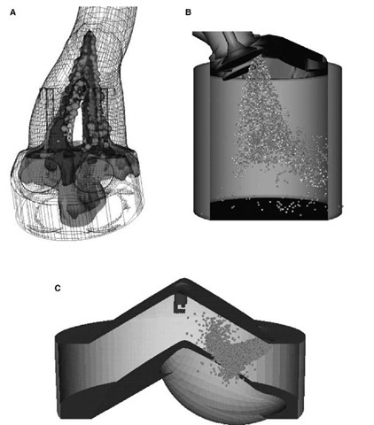
During cold start, a film of liquid fuel can form in the intake valve area of the port and some portion of it is drawn into the cylinder during induction, as shown in Fig. 10A. The fuel delivered to each cylinder can also differ from that metered by the injector, causing a fuel delivery delay and an associated metering error. Thus, extra fuel may be needed for cold starting, causing increased unburned hydrocarbons emissions.
With Gasoline Direct Injection (GDI), which is also called Direct Injection Spark Ignition (DISI), fuel is injected directly into the combustion chamber (Fig. 10B). This leads to higher fuel efficiency, better drivability, and better cold-start performance.[25] However, GDI engines suffer from higher hydrocarbon emissions at light-load, hampering introduction in some markets.
There are three GDI operation regimes.[25] The simplest use early injection to create a homogeneous stoichiometric mixture, and throttling for load control. Cooling due to vaporization of injected fuel allows for the use of higher compression ratios and lower octane fuels without knock (uncontrolled fast combustion). The next regime uses a lean homogeneous mixture with reduced throttling for greater load control. In practice, lean homogeneous operation is less desirable than heavy dilution with Exhaust Gas Recirculation (EGR) to reduce throttling since overall lean operation precludes the use of a three-way catalyst and requires more elaborate lean-NOx after-treatment approaches, such as storage catalysts.
Fig. 6 Cummins diesel engine (A) in-cylinder CFD surface mesh, (B) finite element piston mesh, (C) predicted temperature distribution on head, liner, and piston.
The greatest benefit of GDI is operation in the third regime, which is GDI sans throttling with an overall lean stratified mixture at part load and late-injection. This strategy should smoothly transition to homogeneous charge operation by injecting a larger mass of fuel early in the cycle. Engines utilizing all three GDI modes require complex control systems.
Accurate fuel delivery makes it possible to operate with more dilute mixtures and less cycle-to-cycle variation. Visualization experiments have provided substantial insights into mixture preparation and the causes of cyclic variability in ignition and combustion.[25'26] An inherent disadvantage of lean and stratified GDI engines is that with light-load operation, a three-way catalyst cannot be used effectively for NOx control due to excess air in the exhaust stream. In addition, since the location of the ignition source is fixed, the mixture cloud must be controlled both temporally and spatially for optimal spark ignition, requiring precise matching of fuel injection and in-cy-linder flow fields. CFD modeling has been useful for design,[24] and spark-ignition kernel growth and flame propagation models based on front tracking techniques, or flamelet models have been developed for the simulations.[27]
Two mixing concepts have been proposed: the “wide spacing” concept,[28] where the injector is side-mounted and fuel is injected toward the piston surface and deflected toward the spark plug (see Fig. 10C).[24] Spray momentum is independent of engine speed, and is the driving force for air-fuel mixing; adequate mixing can thus be realized over a wide range of engine speeds. The “close spacing” or “spray-guided” concept, with central injector placement (see Fig. 10B), is often seen in homogenous charge GDI engines,[23] but is also under development as a means to increase the speed-load range over which highly stratified operation can be maintained.[29] To improve the transition between low load and high load operation, optimally timed split injections during intake and compression have been proposed.[30]
HCCI ENGINES
There is great current interest in Homogeneous Charge, Compression Ignition (HCCI) engines for both light-duty automotive (gasoline and diesel) and heavy-duty diesel engines due to its potential for very low emissions and high fuel efficiency. In these engines, a mixture of fuel, air, and recycled combustion products is compressed until it auto-ignites.[31] Unlike diesel engines, combustion is not controlled by the fuel injection, and unlike spark-ignited engines, no discernable flame front is evident. At light load, low temperature combustion leads to more than 90% lower NOx emissions compared to conventional diesel engines.[32] Low soot emissions are also generally found. Unburned hydrocarbon emissions can increase with fuel deposition or lean operation (at low loads), but can be reduced with available exhaust gas oxidation catalysts. Fuel impingement can be reduced with low pressure, low penetration sprays. The requirement to use lean air-fuel mixtures limits the achievable power, favoring the use of high boost.
Fig. 7 (A) Fuel sprays with soot iso-surfaces (dark region at spray tips) during combustion, (B) measured and predicted cylinder pressure at steady-state test points for a heavy-duty diesel engine.
Fig. 8 Measured and predicted soot-NOx tradeoff for a heavy-duty diesel engine. (A) single and (B) double injection (1600 rev/min, 75% load). Numbers indicate start-of-injection timing in crank-angle degrees, where negative numbers are before TDC in the compression stroke and positive numbers are after TDC.
Challenges to HCCI operation include the fact that there is no direct method for controlling the start-of-com-bustion timing, leading to poor fuel efficiency. Ignition is controlled by chemical kinetics, and influenced by the fuel composition, mixture stoichiometry, and the thermo-dynamic state of the mixture. There are no external controls, such as the fuel injection or spark timings used in diesel or SI engines, respectively. However, charge stratification using multiple injection strategies has been explored for combustion phasing and heat release rate control.[33] Due to the rapid auto-ignition heat release, true HCCI combustion approaches the idealization described in the first section. This rapid heat release can cause engine noise and potentially damage the engine, and this places constraints on the maximum load or mixture strengths that can be used. Diesel ignition delay can be extended to allow time for mixing by using very early injection or late injection, as in Nissan’s Modulated Kinetics (MK) concept.[34]
CONCLUSIONS
This entry provides a review of diesel and gasoline engine operating principles, and an introduction to current research issues and literature. Developments in engine hardware, coupled with advanced analysis techniques, such as computer modeling, allow efficient exploration of the large number of possible design configurations. As an example of current technology, the combustion chamber geometry can be optimized using computer modeling for low emission, high efficiency engine operation.[35]
Fig. 9 Mechanism of emission reduction with multiple injections.
Fig. 10 Gasoline engine fuel-air mixing (A) Port Fuel Injection (PFI).
