Abstract
Cooling is necessary to many industrial processes, such as power generation units; refrigeration and air conditioning plants; and the manufacturing, chemical, petrochemical, and petroleum industries. As recently as 20 years ago, cooling towers were more the exception than the rule in the industry because of their high operating cost and the large capital required for their construction. Due to the recent stringent environmental protections, cooling towers became more common. Cooling towers range in sizes and types. Wet, dry, and hybrid are the main types, and each type has many variations in design according to the way the fluids are moved through the system. Some of the advantages and disadvantages of these types, methods of determining their performance, and some terminology common to the cooling industry are presented in this entry.
INTRODUCTION
Most industrial production processes need cooling of the working fluid to operate efficiently and safely. Refineries, steel mills, petrochemical manufacturing plants, electric utilities, and paper mills all rely heavily on equipment or processes that require efficient temperature control. Cooling water systems control these temperatures by transferring heat from hot process fluids into cooling water. Through this process, the cooling water itself gets hot, and before it can be used again, it must either be cooled or be replaced by a fresh supply of cool water.
A cooling system in which the water used in cooling processes or equipment is discharged to waste is called once-through cooling. Characteristically, it involves large volumes of water and small increases in water temperature. Once-through cooling is usually employed when water is readily available in large volume at low cost. Common sources are rivers, lakes, and wells, where the only cost involved is that of pumping. But with today’s need for water conservation and minimal environmental impact, industry is turning more and more to recycling water in what are called cooling towers.
Recently, cooling towers are becoming widely used in most industrial power generation units; refrigeration and air conditioning plants; and the manufacturing, chemical, petrochemical, and petroleum industries to discard waste heat to the environment. They range in sizes—the smallest cooling towers are designed to handle water streams of only a few litres of water per minute supplied in small pipes like those in a residence, whereas the largest cool hundreds of thousands of litres per minute supplied in pipes as huge as 5 m in diameter in a large power plant.
Cooling towers are believed to be only the direct contact type heat exchangers. They can be direct or indirect, however, and they are also characterized in many other different ways based on the type of fluid being used in the cooling process, the means by which the fluids are moved, and the way the two fluids (hot and cold) move with respect to each other. Description of these types, some of their advantages and disadvantages, and methods of estimation of their performance are discussed in the following sections. Some useful terms common to cooling towers industry are also given. This information is a collection of materials published in the list of references and Web sites at the end of this article.
TYPES OF COOLING TOWERS
Cooling towers are classified mainly on the basis of the type of fluid used in the cooling process—water or air. These are three types: wet (evaporative), dry (non-evaporative), and wet-dry (called hybrid).
Wet Cooling Towers
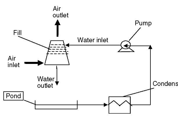
The wet type is more common in large cooling towers, such as in electrical power generation. It is a direct contact heat exchanger, in which hot water from the condenser and cooling air come into direct contact. The water flows in either open circuit or closed circuit. In open circuit, cooling water is pumped into a system of pipes, nozzles, and sprayers within the tower, and is drawn by gravity into a pond below (Fig. 1). Air from the atmosphere enters the tower from the bottom of the tower and flows upward through the falling water. The two fluids go through a material that is provided to increase the surface area of contact between them, which is called packing (or fill). The heated and moisture-laden air leaving the fill is discharged to the atmosphere at a point remote enough from the air inlets to prevent it from being drawn back into the cooling tower. The water is collected at the bottom of the tower and then recirculated to remove more heat from the condenser. The temperature of the cold water entering the condenser will determine the steam condensate temperature and, hence, the backpressure, which impacts the efficiency of the whole power generation system.
Fig. 1 Open-circuit cooling tower.
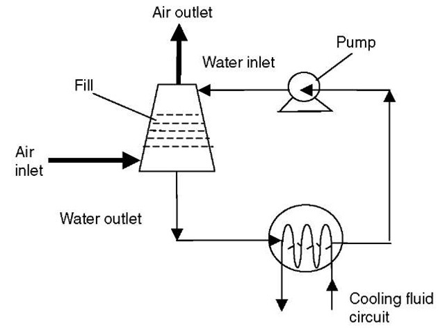
The closed-circuit cooling tower (Fig. 2) involves no direct contact of the air and the liquid—usually, water or a glycol mixture—that is being cooled. This cooling tower has two separate fluid circuits. Water is recirculated in an external circuit outside a closed circuit made of tube bundles or coils containing the hot fluid being cooled. Air is drawn through the recirculating water cascading over the outside of the hot tubes, providing evaporative cooling similar to an open cooling tower. In operation, the heat flows from the internal fluid circuit, through the tube walls of the coils, to the external circuit and then (by heating of the air and evaporation of some of the water) to the atmosphere. Operation of the closed cooling towers is very similar to the open cooling tower, therefore, with one exception: the process fluid being cooled is contained in a “closed” circuit and is not exposed directly to the atmosphere or the recirculated external water.
Fig. 2 Closed-circuit cooling tower.
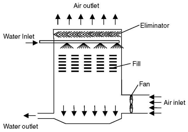
Fig. 3 Mechanical-draft counter-flow tower.
Closed systems offer the advantages of precise temperature control (which is critical in many process applications) and low treatment cost. Because a secondary cooling system and heat exchangers are needed to cool the closed system, higher capital and operating costs are disadvantages of this design.
Mechanical and Natural Draft
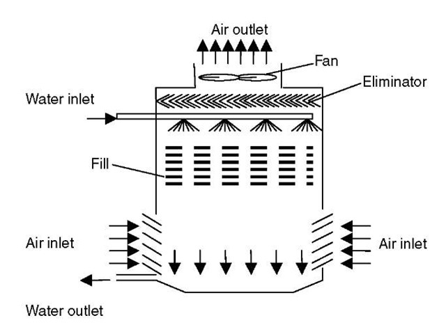
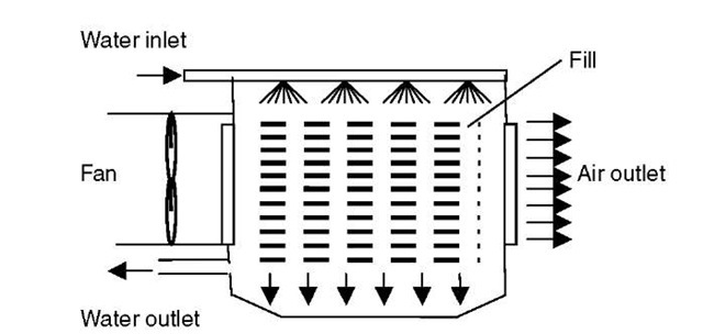
In wet cooling towers, there are two types, based on the mechanism by which air is being circulated: mechanical draft and natural draft. The mechanical draft uses fans (one or more) to move large quantities of air through the tower. The mechanical draft is again divided into two types, based on the location of the air fan: forced and induced. In the case of the forced draft, the fan is located at the air entry at the base of the tower; in the induced draft, the fan is located at the air exit at the top of the tower. The induced draft produces more uniform airflow, which enhances its effectiveness over the forced draft and reduces the possibility of exhaust air recirculation.
There are many configurations of mechanical draft cooling towers that depend on the way the two fluids flow with respect to each other, such as counter flow, cross flow, and mixed flow. In a counter-flow cooling tower, air travels upward through the fill opposite to the downward motion of the water (Figs. 3 and 4).
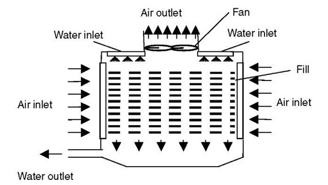
In a cross-flow cooling tower, air moves horizontally through the fill as the water moves downward (Fig. 5 and 6). In a mixed-flow tower, air moves in a direction that is a combination of a counter flow and a cross flow. Cross-flow towers have greater air intake area, which results in considerably lower towers. This means that they have low pressure drop in relation to their capacity and lower fan power requirement, leading to lower energy costs, but the risk of recirculation increases in tower exhaust air. On the other hand, counter-flow arrangements occupy less floor space than cross-flow towers but are taller for a given capacity, so they require higher pump heads. It shows better tower performance, since, the driest air contacts the coldest water, producing higher driving force to the heat.
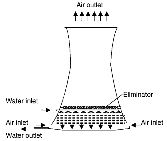
A natural-draft tower is a large chimney and typically has a hyperbolic profile, which is chosen for its structural capability of withstanding wind-induced stresses and vibration; also, it requires less material. The design creates a chimney effect that causes air to move by natural convection through the fill region, which is located inside the base of the chimney (Fig. 7). As the air gets warmer from the contact with the cooling water, it gets lighter; buoyancy forces drive the air to the top of the tower and into the atmosphere, and draw fresh air into the bottom of the tower. The major economical advantage of natural-draft cooling towers is the extremely low auxiliary power consumption. Because there are no rotating parts, operational safety and low maintenance costs are maintained. The great distance between air inlet and air exit in the cooling tower prevents any hot-air recirculation back to the chimney that would otherwise reduce the performance of the cooling tower. The immediate vicinity is not affected by plumes from the cooling tower, because the hot-air exit is situated at a very high elevation. The only drawback to natural-draft towers is that they are large.
Fig. 4 Induced-draft counter-flow tower.
Fig. 5 Mechanical-draft cross-flow tower.
There is also the assisted-draft tower, which is a natural-draft tower with some fans added at the air entry that help reduce the size of the tower. Natural-draft towers are also divided into counter flow and cross flow, defined in a similar fashion to the mechanical-draft towers.
Heat Exchange in Wet Cooling Towers
The type of heat rejection in a wet cooling tower is termed evaporative, in that it allows a small portion of the water being cooled to evaporate into a moving air stream to provide significant cooling to the rest of that water stream. The heat from the water stream transferred to the air stream raises the air’s temperature and its relative humidity to 100%, and then this air is discharged to the atmosphere. The ambient air wet-bulb temperature is the controlling factor in recirculated systems and will determine the steam condensate temperature. Evaporative-heat rejection devices such as cooling towers are commonly used to provide significantly lower water temperatures than are achievable with air-cooled or “dry” heat rejection devices. The evaporative process enhances the performance of wet cooling towers over dry cooling towers severalfold due to the change in both sensible and latent heats.
Consequences and Concerns for Wet Cooling Towers
Wet cooling towers are the most common type due to their high effectiveness, but there are some drawbacks. If cooled water is returned from the cooling tower to be reused, as in the circulating systems, some water must be added to replace, or make up, the amount of the water that evaporates. Because evaporation consists of pure water, the concentration of dissolved minerals and other solids in circulating water will tend to increase unless some means of dissolved-solids control (such as blow-down) is provided. Blow-down is the amount of the circulating water that is removed to maintain the quantity of dissolved solids and other impurities at an acceptable level. Some water is also lost from droplets being carried out with the exhaust air (drift). The makeup amount must equal the total of the evaporation, blow-down, drift, and other water losses (such as wind blow-out and leakage) to maintain a steady water level. Devices such as wind screens, louvers, splash deflectors, and water diverters are used to limit these losses.
Fig. 6 Induced-draft cross-flow tower.
The magnitude of drift loss is influenced by the number and size of droplets produced within the cooling tower, which in turn are determined by the fill design, the air and water patterns, and other interrelated factors. Drift is typically reduced by installing bafflelike devices, called drift eliminators, through which the air must travel after leaving the fill and spray zones of the tower to collect the droplets. Tower maintenance and operation levels can also influence the formation of drift, such as excessive water flow, excessive airflow, or bypassing the tower drift eliminators can increase drift emissions. Types of drift-eliminator configurations include herringbone (blade-type), wave form, and cellular (or honeycomb). The cellular units generally are the most efficient. Drift eliminators are made of various materials, such as ceramics, fibre-reinforced cement, fibreglass, metal, plastic, and wood.
Fig. 7 Natural-draft cooling tower.
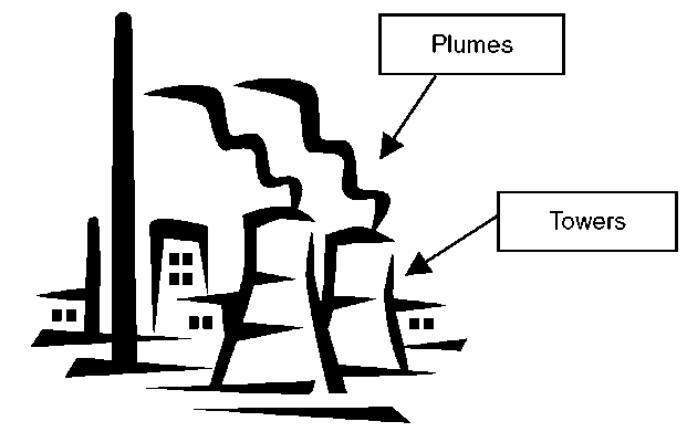
Fig. 8 Visual plume from cooling towers.
Other unfavourable environmental impacts of wet cooling are pollutant discharge—e.g., zinc, chlorine, and chromium (chromium is used to protect cooling-system equipment from corrosion)—to the atmosphere. The spread of Legionnaires’ disease is due to the bacteria that thrive at temperatures typical in wet cooling systems and that can be transported through air aerosols formed in cooling towers. Other impacts are mineral drift and the formation of visual plumes. Under certain conditions, a cooling-tower plume may present fogging or icing hazards to its surroundings (Fig. 8).
Types of Fill (Packing)
The fill may consist of multiple vertical, wetted surfaces upon which a thin film of water spreads (film fill); several levels of horizontal splash elements, which create a cascade of many small droplets that have a large combined surface area (splash fill); or trickle, which is a combination of the film- and splash-type fills. A wide variety of materials and geometries have been used for packing, such as corrugated roofing sheets made of cement-based or plastic material, timber laths of triangular or rectangular cross section, plastic-impregnated paper honeycomb, and complex cellular geometries made of thin plastic material.
Thermo-Fluid Dynamic Efficiency in Cooling Towers
To choose the most convenient fill, you need to find the one that produces the maximum heat transfer with the minimum pressure drop. Other factors to be considered are the physical and chemical characteristics required for the water to cool, fouling properties, suspended materials, etc. Sirena[1] has suggested a Thermo-Fluid Dynamic Efficiency that can be used to compare and select a fill material for a particular application. This efficiency is defined as the ratio of the number of units of diffusion to the pressure drop coefficient. In this paper, the pressure drop coefficient is given for some commercial fill materials. Al-Nimr[2] has studied the dynamic thermal behaviour of cooling towers containing packing material and was able to predict closed form solutions for the transient and steady performance of a counter-flow cooling tower.
Dry Cooling
Dry cooling towers transfer heat to the atmosphere without the evaporative loss of water. Dry cooling is capable of only smaller temperature variations (around 10°C), unlike wet cooling. Similar to wet cooling, there are two types of dry cooling: direct and indirect. Direct dry cooling systems utilize air directly to condense steam, which is exhausted from the turbine into ducts and headers for distribution into rows of small-diameter finned tubes (i.e., heat exchanger). Indirect dry cooling, which is also known as the Heller System, utilises a closed-cycle water cooling system as the primary coolant to condense steam, and the heated water is air cooled. The cooling water flows through bundles of tubes with air flowing over them, but the cooling air never comes into contact with the cooling water. In both systems, direct and indirect, the flow rate of air required to achieve the same cooling capacity will have to be three or more times greater than in a wet cooling tower, so the tower will have to be much larger and more expensive.
Cooling towers are also characterized by the means by which air is moved. Similar to wet cooling towers, dry cooling towers can be mechanical draft, natural draft, or fan-assisted draft. Mechanical-draft towers rely on power-driven fans to draw or force the air through the tower. Natural-draft cooling towers use the buoyancy of the exhaust air rising in a tall chimney to provide the draft. A fan-assisted natural-draft cooling tower employs mechanical draft to augment the buoyancy effect. Many early cooling towers relied only on prevailing wind to generate the draft of air.
In power generation applications, the heat transfer between air and cooling water is achieved by convection, and the driving force of this cooling process is the approach temperature (which is defined as cooling water temperature at outlet and air temperature at inlet)—not by evaporation, as in a wet cooling tower. Some of the advantages of dry cooling towers are that they do not need any makeup cooling water or water treatment and they do not generate plume, fog, mineral drift, and disposal issues associated with wet cooling. Size is a concern in dry cooling systems, however, because dry cooling is not as effective as wet cooling; the towers have to be much larger to achieve comparable heat rejection. Another challenge to direct dry cooling is operational control in regard to how to balance the steam flow to keep the desired steam condensation temperature (and, hence, turbine backpressure), which varies with loading. Other disadvantages of dry cooling are increase in noise, plume recirculation, maintenance of many components, and energy penalties caused by the variations of daily temperature and increases in air emissions.
Dry-cooling performance depends on the ambient air dry-bulb temperature (i.e., the sensible heat) instead of the wet-bulb temperature in the case of a wet cooling tower. Dry cooling becomes more economical when the approach temperature becomes considerably high. Other factors that affect the performance of dry cooling towers are the crosswind speed and the way that the heat exchanger bundles are arranged. The effect of crosswinds at different speeds and the effect of adding windbreak walls on the thermal performance of natural-draft dry cooling towers is given by Al-Waked and Behnia.[3] The effect of arranging the heat exchanger bundles—either vertically around the circumference of the tower or horizontally in the inlet cross section of the tower—is given by du Preez and Kroger.[4]
Wet-Dry Cooling (Hybrid)
Combined wet-dry cooling towers were introduced due to the recent stringent environmental protection laws. These towers effectively suppress detrimental plume formation at an efficiency level comparable to that of wet cooling towers. In hybrid wet-dry systems, the hot water from the power station condenser is cooled to the design discharge temperature as it passes in series first through the dry section and then through the wet section of the tower. The low-humidity hot air stream from the dry system is mixed with the moist warm air, leaving the tower at humidity levels sufficiently low to prevent the formation of visible plumes. The wet and dry components can be used separately or simultaneously for either water conservation or plume abatement purposes. At low ambient temperatures, the cooling tower can be operated as a dry cooling tower only, whereas at high temperatures, it can be used as a wet cooling tower only to achieve the required cooling without the risk of plume formation; the dry air is not put into operation until the ambient temperature starts to fall.
The design and construction of hybrid cooling towers are more complicated, and according to Streng,[5] the following data need to be specified for winter and summer operation. These data are thermal performance; cooling water flow or cooling range, which is the difference between the water temperature at inlet and the water temperature at outlet; ambient temperature; criteria for operating without plume; sound attenuation regulations; and limitations with respect to the erection area or overall height and operating weight and water analysis of the makeup water. In his work,[5] the construction, including material selection and automatic operation of the cooling system, is discussed in detail.
When a combination of wet and dry cooling technology is used, depending on system configuration, water consumption can approach that of recirculating wet systems or can be much lower. Design studies have ranged from 30 to 98% reduction in water use compared with all wet recirculating systems. As the hybrid cooling towers conform well to the stringent environmental protection requirements and to the standard operation reliability set for cooling systems, it is expected, therefore, that they will become more widespread.[5]
PERFORMANCE AND RATING OF COOLING TOWERS
In power generation, lower turbine backpressures are achieved when steam condensate temperatures are lower. Designing and operating a cooling system that can remove the heat of condensation consistently and continually at those low temperatures is essential. Therefore, the cooling system should be considered to be an integral part of the power generation process that can have a major influence on overall power plant performance and availability.
The choice of an appropriate cooling tower for a special application depends on many factors, such as capacity, availability, reliability, cost, and effectiveness. The effectiveness of a cooling tower is defined as the ratio of the actual energy that is exchanged to the maximum energy that could possibly be exchanged. The number of transfer units (NTU) is another parameter that measures the heat transfer size of the cooling tower. The higher the NTU value, the closer the cooling tower is to its thermodynamic limit. To estimate cooling-tower effectiveness and NTU, different analyses are used (similar to the ones used for analysing heat exchangers) that depend on the particular type under consideration.
The thermodynamic performance of any wet cooling tower is a function of the geometry and the ratio of the water flow rate (L) to the gas flow rate (G)—i.e., LIG. This value is quantified by means of a parameter known as the tower characteristic or number of diffusion units t] (7] = KaV/L), where K is the average mass transfer coefficient of condensed steam, a is the area of transfer surface per unit volume, and V is the effective volume. Manufactures supply charts for their cooling towers that present the tower characteristics as a function of LIG and the difference between the (outlet cooling water temperature (CWT) and air wet-bulb temperature (WBT).
Cooling-tower performance can be specified from the following parameters: water mass flow rate, inlet and exit temperature of water, and atmospheric wet- and dry-bulb temperatures of air. Many researchers have attempted to analyze wet cooling systems to estimate their performance. A basic theory of wet-cooling-tower operation was first proposed by Walker.[6] The practical use of basic differential equations, however, was first presented by Merkel,[7] who combined the equations for heat and water vapor transfer. He showed the utility of total heat or enthalpy difference as a driving force to allow for both sensible and latent heats. The basic approximations in Merkel’s theory are
• The resistance for heat transfer in the liquid film is negligible.
• The mass flow rate of water per unit of cross-sectional area of the tower is constant (i.e., there is no loss of water due to evaporation).
• The specific heat of the air-stream mixture at constant pressure is the same as that of the dry air.
• The Lewis number (which relates heat transfer to mass transfer) for humid air is unity.
• The air exiting the tower is saturated with water vapor.
It is important to note that the formulation and implementation of Merkel’s theory in cooling-tower design and rating are presented and discussed in most text topics on unit operations and process heat transfer.
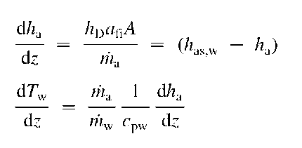
A summary of some of the methods that attempt to evaluate wet cooling towers’ performance has been published by Kloppers and Kroger.[8] They compared cooling-tower performance obtained by Merkel, Poppe, and e-NTU methods. Merkel applied the mass and energy conservation laws to a differential control volume that includes the air and the water in a counter-flow cooling-tower arrangement, and derived the following differential relationships:
where h, enthalpy; kD, mass transfer coefficient; a, surface area per unit volume; A, frontal area; m, mass flow rate; z, vertical direction; cp, specific heat at constant pressure;
where Me, Merkel number; L, length; G, mass velocity; subscript: M, according to Merkel approach; i, inlet; o, outlet.
The term on the right side is a measure of the cooling requirement whereas the term on the left side is a measure of the performance of the packing.
Poppe included the effect of Lewis factor Le (defined as hc/hD cpa) and the reduction in water flow due to evaporation. He derived two equations for the Merkel number based on the state of the air at exit—unsaturated or supersaturated. If the air is exiting as unsaturated, the Merkel number can be obtained by an iterative procedure of integrating the following equation:
The subscript ss = supersaturated. Details can be found in Poppe and Rogener[9] and in Bourillot.[10]
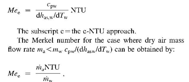
According to the e-NTU method, in which the same simplification of Merkel is used, the Merkel number for
In the above equation, w, humidity ratio; the subscript P, Poppe approach; v, vapor; a, air; s, saturated, and w, water.
The Merkel number for air exits as supersaturated can be obtained by an iterative procedure of integrating the following equation:
subscript: a, air; w, water; s, saturated; fi, fill; (w), evaluated at water temperature Tw.
After the above equations were combined and integrated over the whole length of the tower, the Merkel equation was derived:
C is the fluid capacity rate ratio and is defined as Cmin/Cmax. It is to be noted that the e-NTU method is applicable to the cross-flow arrangements, provided that the air and water streams should be defined, whether they are mixed, unmixed, or a combination.
Khan and Zubair[11] presented an analysis to estimate the effectiveness and NTU of a counter-flow wet cooling tower that matched the experimental data closely. They included in their model the effect of the Lewis number, defined in a similar fashion to Poppe’s as the ratio of the convective heat transfer coefficient to the convective mass transfer coefficient times the specific heat at constant pressure of moist air, the heat resistance in the air-water interface, and the effect of water evaporation on the air states along the vertical length of the tower. In their analysis, they assumed constant convective heat and mass transfer coefficient, and ignored the heat lost through the tower walls, variation in specific heat properties, and water lost by drift. They applied the mass and energy conservation equations to a differential volume to relate the change in enthalpy of moist air to its humidity ratio, in terms of Lewis number Le and other properties of moist and saturated air. The outlet properties are obtained by numerically integrating the set of differential equations of conservation of mass and energy on an increment volume of the cooling tower.
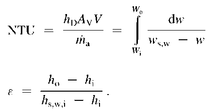
They also gave the following definition of NTU and effectiveness:
Av, surface area of water droplet per unit volume of the tower; V, tower volume; subscript: o, outlet, and i, inlet.
They also gave an empirical equation for NTUem:
c and n, empirical constants specific to a particular tower design, and subscript em, empirical.
Another approach is to return to the fundamental equations of fluid mechanics and heat and mass transfer, and arrive at numerical solutions with the aid of computational fluid dynamics technique (CFD). Some examples are the work by Al-Waked et al.[12] and Hasan et al.[13] among many others. These solutions can in
where NTU is given by:
principle be used as the sole basis of design or they can be used to examine, modify, and improve existing simpler methods—such as work by Kloppers and Kroger,[14] who used the finite difference method to compare the three approaches of Merkel, Poppe, and e-NTU.
CONCLUSION
The different types of cooling towers—wet, dry, and hybrid—have been presented. Research and experience show that the hybrid cooling towers conform well to the stringent environmental protection requirements and to the standard operation reliability set for cooling systems; it is expected, therefore, that they will become more widespread. Different methods to estimate cooling-tower performance are presented, based on some assumptions that simplify the problem. As the systems get more complicated, however, CFD is capable of predicting performance and can be used as the sole basis of design, or it can be used to modify and improve existing simpler methods to make them closer to reality.
Glossary
Approach temperature: The difference between the temperature of the condenser water leaving the tower and the wet-bulb temperate of the air entering the tower in the case of the wet tower and the dry-bulb temperature of the air entering the tower in the case of the dry tower.
Blow-down: The quantity of the circulating water that is removed to maintain the amount of dissolved solids and other impurities at an acceptable level.
Blow-out: Water droplets blown out of the cooling tower by wind—generally, at the air inlet openings. In the absence of wind, water may also be lost through splashing or misting.
Drift: Water droplets that are carried out of the cooling tower with the exhaust air.
Drift eliminator: Equipment containing a complex system of baffles designed to remove water droplets from cooling-tower air passing through it.
Noise: The sound generated by the impact of falling water; the movement of air by fans; the fan blades moving in the structure; and the motors, gearboxes, and drive belts.
Plume: The stream of saturated exhaust air leaving the cooling tower. The plume is visible when the water vapor it contains condenses in contact with cooler ambient air.
Range: The difference between the cooling water temperature entering the tower and the cooling water temperature leaving the tower.
