10.8.1
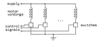
Typical controllers for variable-reluctance stepping motors are variations on the outline shown in Fig. 10.37. Boxes are used to represent switches; a control unit, not shown, is responsible for providing the control signals to open and close the switches at the appropriate times in order to spin the motors. In many cases, the control unit will be a computer or programmable interface controller, with software directly generating the outputs needed to control the switches, but in other cases, additional control circuitry is introduced, sometimes gratuitously.

FIGURE 10.37 Typical controller for variable-reluctance stepping motors.
Motor windings, solenoids, and similar devices are all inductive loads. As such, the current through the motor winding cannot be turned on or off instantaneously without involving infinite voltages. When the switch controlling a motor winding is closed, allowing current to flow, the result of this is a slow rise in current. When the switch controlling a motor winding is opened, the result of this is a voltage spike that can seriously damage the switch unless care is taken to deal with it appropriately.
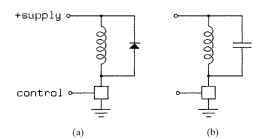
There are two basic ways of dealing with this voltage spike. One is to bridge the motor winding with a diode, and the other is to bridge the motor winding with a capacitor. Figure 10.38 illustrates both approaches.
The diode shown in Fig. 10.38 must be able to conduct the full current through the motor winding, but it will conduct only briefly each time the switch is turned off, as the current through the winding decays. If relatively slow diodes, such as the common 1N400X family, are used together with a fast switch, it may be necessary to add a small capacitor in parallel with the diode.

FIGURE 10.38 Voltage-spike control with (a) a diode and (b) a capacitor.
The capacitor shown in Fig. 10.38 poses more complex design problems. When the switch is closed, the capacitor will discharge through the switch to ground, and the switch must be able to handle this brief spike of discharge current. A resistor in series with the capacitor or in series with the power supply will limit this current. When the switch is opened, the stored energy in the motor winding will charge the capacitor up to a voltage significantly above the supply voltage, and the switch must be able to tolerate this voltage. To solve for the size of the capacitor, we equate the two formulas for the stored energy in a resonant circuit.

where P = stored energy, W • s or C • V C = capacity, F V = voltage across capacitor L = inductance of motor winding, H I = current through motor winding
Solving for the minimum size of capacitor required to prevent overvoltage on the switch is fairly easy.
![]()
where:
Vb = breakdown voltage of the switch Vs = supply voltage
Variable-reluctance motors have variable inductance that depends on the shaft angle. Therefore, worst-case design must be used to select the capacitor. Furthermore, motor inductances are frequently poorly documented, if at all.
The capacitor and motor winding in combination form a resonant circuit. If the control system drives the motor at frequencies near the resonant frequency of this circuit, the motor current through the motor windings, and therefore the torque exerted by the motor, will be quite different from the steady-state torque at the nominal operating voltage. The resonant frequency is
![]()
Again, the electrical resonant frequency for a variable-reluctance motor will depend on shaft angle. When a variable-reluctance motor is operated with the exciting pulses near resonance, the oscillating current in the motor winding will lead to a magnetic field that goes to zero at twice the resonant frequency, and this can severely reduce the available torque.
Variable-Reluctance Motors (Electric Motors)
Next post: Unipolar PM and Hybrid Motors (Electric Motors)
Previous post: BASIC STEPPING-MOTOR CONTROL CIRCUITS (Electric Motors)
