Over the last decade, the electric machine industry has been placing more emphasis on variable- and adjustable-speed operations. Developments in power electronics made it possible to achieve these goals. However, this technology produces pollution to the utility grid and raises power quality issues. This topic describes recent harmonic regulations imposed on power electronic equipments and systems. Merits and demerits of poor power quality drives are also explained. As a solution, various power factor correction (PFC) techniques are introduced for advanced motor drives. Different techniques for active and passive filters, special drive topologies for PFC, and harmonic injection are explained in detail.
Most traditional motor drives are fixed-speed drives. Recent advancements in the power electronic industry have encouraged machine manufacturers to start developing systems for adjustable-or variable-speed/frequency drives. Among the reasons for adopting adjustable-speed drives (ASDs) are better overall performance, improved efficiency, and reduced hardware complexity. Power
electronics is used as an interface between the utility and motor. In other words, the machine is driven by a power electronic interface rather than the utility supply. The obvious reason is to achieve a variable form of supply, which is not available from the utility. By adjusting this variable supply, machine performance can be optimized. A typical advanced electric motor drive architecture is shown in Fig. 10.1. In the figure, the utility supply can be single phase or three phase. The machine can be single phase, three phase, or even multiphase, depending on the performance requirement. The power electronic system is designed in a way such that the machine can be optimized for its own performance independent of the available supply. Sensors can be Hall-effect or it is also possible to achieve sensorless drives.
The increased use of ASDs in power systems have led to a major problem for power quality. ASDs along with their power electronic drives appear as nonlinear loads to the utility grid or power system. In general, any power electronic driven system imposes power quality
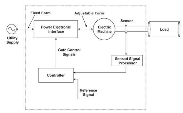
FIGURE 10.1 Advanced electric motor drive architecture.
issues, i.e., power factor deterioration and harmonic distortion. The solution to these problems also resides in power electronics. Figure 10.2 shows the input current of a typical ASD. The harmonics of orders 5 and 7 are considerably high. Any electric motor drive system can be simplified, as shown in Fig. 10.3.
If the load is linear or the machine is directly connected to the mains, the supply voltage and current waveforms are sinusoidal and the power factor is given as follows:
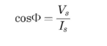
However, advanced electric motor drives usually consist of a diode bridge rectifier followed by a bulk capacitor and the power processing stage. The bulk capacitor is used to smooth the output voltage
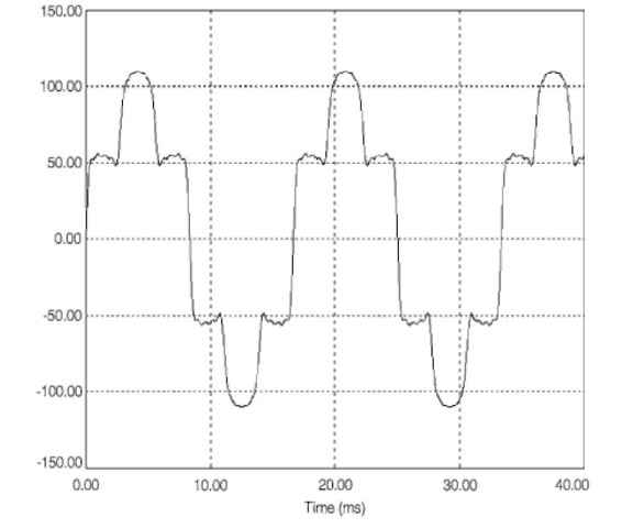
FIGURE 10.2 Input current of a typical ASD.
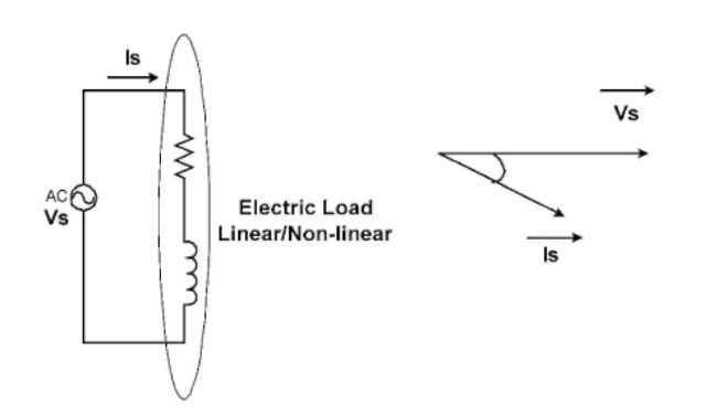
FIGURE 10.3 Simplified electric motor drive system.
waveform. The diode network and the capacitor draw current from the mains only when the instantaneous mains voltage is greater than the capacitor voltage. This results in a nonsinusoidal supply current waveform. In this case, the power factor is not given by the above simple equation. Now the power factor is defined as
![tmpC-5_thumb[2] tmpC-5_thumb[2]](http://lh6.ggpht.com/_X6JnoL0U4BY/S1guEF2R_4I/AAAAAAAAH2E/zqB-bXzyuLE/tmpC-5_thumb%5B2%5D_thumb.jpg?imgmax=800)
where DPF is the displacement power factor and THD is the total harmonic distortion. DPF and THD are defined as follows:
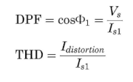
where Is1 is the fundamental component of the supply current. Since the capacitor is chosen for a certain hold-up time, its time constant is much greater than the frequency of the mains. This implies that the instantaneous mains voltage is greater than the capacitor voltage only for very short periods of time (charging time of capacitor). During
this time the capacitor must charge fully. Therefore, large pulses of current are drawn from the line over very short periods of time. This is true of all rectified AC sine wave signals with capacitive filtering. This causes the following problems:
• Creation of harmonics and electromagnetic interference (EMI)
• High losses
• Required overdimensioning of parts
• Reduced maximum power capability from the line
Power factor correction makes the load look more like a resistive element than would be the case without PFC. Modern PFC circuits can achieve power factors very near to unity. PFC circuits have the following advantages:
• Better source efficiency
• Overall lower power installation cost
• Lower conducted EMI
• Reduced peak current levels
• Act as filters for the conducted EMI
• Make possible common input filtering for paralleled supplies because the loads all appear to be resistive
• Better chance of agency approval
However, PFC circuits have one or more of the following disadvantages:
• Introduce greater complexity into the design
• Have more parts, adversely affecting reliability and cost
• Generation of EMI and radiofrequency interference (RFI) requires extra filtering, making the input filter more complex and more expensive
• Higher system cost
Harmonic standards developed by IEEE and IEC are enforced in many parts of the world including Europe. Therefore, PFCs have attracted a lot of attention in the power electronic industry. In most applications, it is not difficult to meet these standards; however, the
most economic choices are still being developed. IEEE and international harmonic standards can be grouped into three main categories:
1. Customer system limits:
• IEEE 519-1992
• IEC 1000-2-2 (compatibility levels)
• IEC 1000-3-6
2. Equipment limits:
• IEC 1000-3-2
• IEC 1000-3-4
• New task force in IEEE (harmonic limits for single-phase loads)
3. How to measure harmonics
• IEC 1000-4-7
The IEC 1000 series deals with electromagnetic compliance. Part 3 sets limits and Series 2 addresses limiting harmonic current emission for equipment input current less than or equal to 16 A. IEC 1000-3-4 not only deals with individual equipment, but also sets limits for the whole system installation. Both single-phase and three-phase harmonic limits are addressed in this section of the regulation. On the other hand, IEEE standard 519 sets limits of harmonic voltage and current at the point of common coupling (PCC). The philosophy behind this standard is to prevent harmonic currents traveling back to the power system and affecting other customers.
Utility Interface Issues (Electric Motor)
Next post: ASD EXAMPLE (Electric Motor)
Previous post: ENERGY CONVERSION CYCLE (Electric Motor)
