6.2.6
When designing a single-phase motor, thought must be given to the auxiliary winding in starting, and in the case of capacitor or two-value-capacitor motors, two-winding performance must be considered. The following points come to mind:
1. Does the motor have sufficient starting torque? Does it have sufficient torque when switching out the starting winding to bring the motor up to speed?
2. If the motor includes a capacitor, what is the voltage across the capacitor?
3. What is the performance when both auxiliary and running windings are energized at all times, as with a permanent-split-capacitor (PSC) or two-value-capacitor motor?
4. What is the starting current?
The following assumptions are made here:
• The auxiliary and main windings are electrically orthogonal to each other.
• Each winding produces a double revolving field. Therefore, we have two forward and two backward fields produced by the auxiliary and running windings.
• Following the previous discussion of operations of a single winding, then both the running and auxiliary winding have a forward and backward equivalent circuit, with one additional change. Each of the four revolving fields induces a speed voltage in the other winding. That is, the forward-revolving fields and the backward-revolving fields induce voltages in the forward and backward circuits of the other, and vice versa. This amounts to four dependent voltage sources. These speed-voltage terms can be seen in the q-d transformation matrix equation, Eq. (6.86), where cor appears.
• The two windings are arranged such that the forward field of the auxiliary winding induces a speed voltage in the main winding that lags the forward field by 90°.This implies that the main winding is displaced 90° ahead of the auxiliary winding in space, causing a forward-revolving field.
Before proceeding with the double-revolving-field theory, it is worth mentioning that there are other approaches to this problem—namely, the cross-field theory; the use of symmetrical components; and the q-d transformation approach, which is mentioned but never pursued in the preceding sections.
The voltage induced by forward and backward fields can then be represented as follows. The forward and backward voltages induced in the main field winding due to the forward and backward fields of the main winding are
![]()
![]()
The forward and backward voltages induced in the auxiliary field winding due to forward and backward fields of the auxiliary winding are

where a is the turns ratio of auxiliary winding turns to main winding turns
![]()
Note that these four voltages are current dependent and appear in the forward and backward field circuits and are indicated in Fig. 6.18.
We next concern ourselves with the speed voltages induced into the main and auxilary windings by the auxilary and main double revolving fields, respectively. It has previously been indicated that the voltage induced in the main winding by the forward revolving field of the axiliary field lags 90° behind the voltage Efa. On the other hand, the voltage induced into the main winding by the backward revolv-
![]()
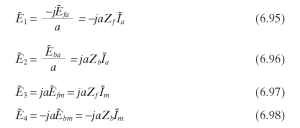
Figure 6.18 is redrawn as Fig. 6.19 to simplify the circuit.
Included in the circuit is one impedance Ze which represents an external component which may be added to the auxiliary winding to enhance performance. For example, it could be (1) resistance split-phase operation, (2) capacitance which is
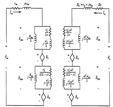
FIGURE 6.18 Single-phase motor equivalent circuit for combined winding performance.
removed after starting (capacitor start motor), (3) a change in capacitance (two-value-capacitor motor), or (4) a fixed capacitance (PSC motor).
r2 and x2 are now the resistance and reactance, respectively, of the rotor referred to the main winding; that is

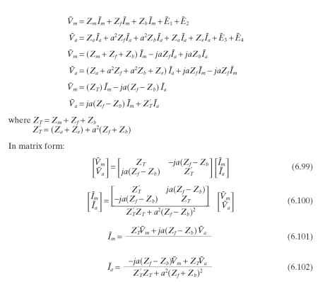
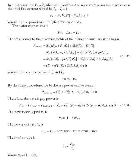
Writing the voltage equations around each winding gives the following:
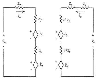
FIGURE 6.19 Simplified single-phase motor equivalent circuit.
