8.4
Brushless DC motor drives require rotor position information for proper operation. Position sensors are usually used to provide the position information for the driver. However, in sensorless drives, position sensors are not used. Instead, position information is obtained indirectly. Advantages of sensorless drives include increased system reliability, reduced hardware cost, reduced feedback units, and decreased system size. In addition, they are free from mechanical and environmental constraints. However, sensorless techniques may affect system performance. Low-speed sensorless operation is also difficult.
Many model-based sensorless techniques have been proposed.
In these methods, a model of the machine is used to obtain the position information from measured signals such as voltages and currents. Based on the model, usuallya linear or nonlinear equation for position is solved. For example, in a d-q model-based sensorless technique, the actual d-q transformed currents and voltages, those on a hypothetical axis offset from the d-q axis by a small angle A6, the output voltages of the model on the hypothetical axis, and those on
the actual d-q axis are compared. The difference between the calculated voltages of the hypothetical axis considering A6 = 0 and the actual d-q axis voltages on the hypothetical axis considering A8 gives the actual change in rotor position from the previously known position.
Many sensorless techniques are based on the back EMF of the machine. Generally,
these techniques are used for BLDC machines with trapezoidal back EMF. For example, the zero crossing point of the back EMF voltage can be detected. In this scheme, the three terminal voltages and neutral voltage of the motor with respect to the negative DC bus voltage are measured. The terminal voltage is equal to the neutral voltage at the instants of the zero crossing of the back EMF waveform. In order to use the zero crossing point to derive the switching sequence, this point has to be shifted by 30 degrees. Therefore, in this method, speed estimation is required.
In the third-harmonic back EMF sensing technique,
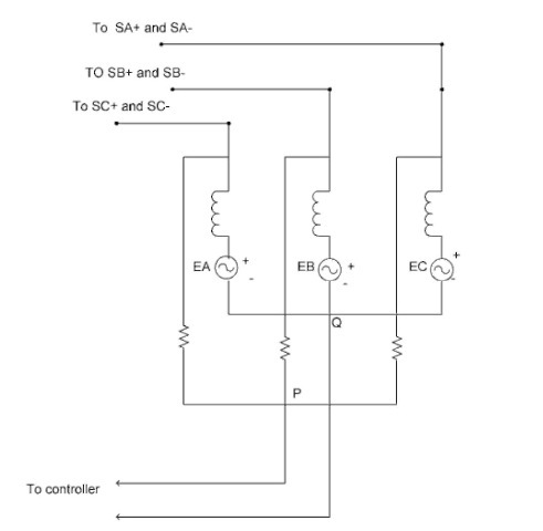
the position of the rotor can be determined based on the stator third-harmonic voltage component. To detect the third-harmonic voltage, a three-phase set of resistors is connected across the motor windings (Fig. 8.18). The voltage across the points P and Q is denoted by E3, and it determines the third-harmonic voltage. This voltage is integrated for a zero crossing detector. The output of the zero crossing detector determines the switching sequence for turning on the switches. The resistances and inductances are shown in the circuit of Fig. 8.18. The important point is that the summed terminal voltages contains only the third and the multiples of the third harmonic due to the fact that only zero sequence current components can flow through the motor neutral. This voltage is dominated by the third harmonic.
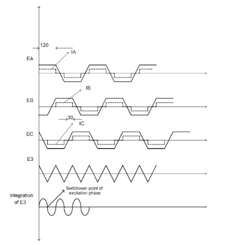
By integrating the voltage E3, we get the third-harmonic flux linkage X3. The third-harmonic flux linkage lags the third harmonic of the phase back EMF voltage by 30 degrees. The zero crossings of the third harmonic of the flux linkage correspond to the commutation instants of the BLDC driver, as shown in Fig. 8.19.
The back EMF integration method is another sensorless technique. In this method, by integrating the back EMF of the unexcited phase, position information is obtained. The integration of the back EMF starts when the back EMF of the open phase

FIGURE 8.18 Resistors for the third harmonic back EMF sensing technique.
crosses zero. Here, speed estimation is not required. A threshold is set to stop the integration, which corresponds to a commutation point. Assuming trapezoidal back EMF, the threshold voltage is kept constant throughout the speed range. Integrating from the zero crossing point (ZCP) to the commutation point (CP) is constant (not a function of speed). Therefore, speed estimation is not required.
The freewheeling diode conduction-sensing technique uses indirect sensing of the phase back EMF to obtain the switching instants of the BLDC motor. Considering the 120-degree conducting wye-connected BLDC motor, one of the phases is always open. After opening the phase for a short interval of time, there remains a phase current flowing through a freewheeling diode. This open phase

FIGURE 8.19 Phase currents and back EMF voltages, E3, and integration of E3 versus rotor position.
current becomes zero in the middle of the commutation interval, which corresponds to the point where the back EMF of the open phase crosses zero.
Some sensorless techniques are also based on the magnetic flux. These methods are usually used for BLDC motors with sinusoidal back EMF. For example, in flux integration methods, instantaneous flux is obtained from the integration of the voltage
equation of the machine. By knowing the initial position, the relationship of the flux linkage to the rotor position, and machine parameters, the rotor position is estimated. The speed is determined by the rate of change of the flux linkage from the integration results.
Observer-based sensorless methods are generally used for BLDC motors with sinusoidal back EMF. In these techniques, a Kalman filter might be used. The Kalman filter provides an optimum observation from noisy sensed signals and processes that are disturbed by random noise. A mathematical model describing the motor dynamics is known. The rotor position can be determined based on the voltages and currents. The measured voltages and currents are transformed to stationary frame components. Using the state equations and a Kalman filter, the missing states (rotor position and velocity) are estimated. The estimated rotor position is used for commutation. The function of the filter is to correct the estimation process in a recursive manner. The filter constantly works on the output and corrects its quality based on the measured values. Based on the deviation from the estimated value, the filter provides an optimum output value at the next output instant.
In a state observer,
the output is defined as a combination of the states. This output is compared with the equivalent measured output of the real motor. Any error between the two signals is used to correct the state trajectory of the observer. The accuracy of the position information depends on the stability of the observer. For the system to be stable, the gain of the system has to be optimized. Furthermore, initial information of the states is required for proper convergence of the observer.
