10.11.3
Specific current waveforms are assumed in each of the motor drive schemes discussed previously. To produce these waveforms from a voltage source requires current control. For maximum efficiency, this current control cannot require sustained operation of the power electronic device in its linear operating region. Rather, devices should act as switches having two states: off, where power dissipation is zero because there is no current flow, and on, where power dissipation is low because the voltage across the device is minimized. As a result, current control is implemented as a switching strategy in which the switch duty cycle is varied according to some error criterion, and the current maintains the correct shape in an average sense only. If switching action occurs at a much higher rate than any variation in the desired current waveform, the deviation between the actual and desired current can be made small. As a whole, these switching strategies are called pulse-width modulation (PWM).
Because PWM is applied in countless applications in addition to motor drives, there are hundreds of articles on PWM in the literature. Many of these articles pertain to voltage PWM, where one seeks to control voltage rather than current (Holtz, 1992). A smaller number pertain to current-control PWM, which is of interest here. As before, the goal is to develop an intuitive understanding, rather than discuss every nuance of every PWM scheme. More detailed information can be found in references such as Holtz (1992),Anunciada and Silva (1991), Brod and Novotny (1985),
and Murphy and Turnbull (1988).
In motor drive applications, PWM is almost always implemented by controlling the bridge switches themselves. However, switching can also be implemented external to the bridge. Moreover, because motor windings have inductance, PWM action causes the phase inductance to charge and discharge, giving a continuous current despite the presence of a discontinuous applied voltage. As discussed earlier and shown in Figure 10.77, inductor discharge can be fast or slow depending on which switch or switches are controlled by PWM. Intelligent use of this capability can lead to improved performance (Freimanis, 1992).
Hysteresis PWM. Hysteresis PWM, conceptually the simplest PWM scheme, controls the on-off state of switches to keep the current within a band around the desired value, as shown in Fig. 10.85. In the figure, I* is the reference current waveform (i.e., the desired current), 2A7 is the tolerance band, I = I* -AI is the lower bound, and I = I* + I is the upper bound. Whenever the current crosses the upper bound, a switch is opened, allowing current to decay or discharge. Likewise, when-
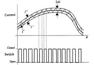
FIGURE 10.85 Hysteresis PWM waveforms.
ever the current crosses the lower bound, a switch is closed, forcing current to climb in amplitude or change. Clearly, the rate at which the inductance involved charges and discharges influences the rate at which switching occurs. In a motor drive, where the voltage across the inductance is a function of the difference between a supply voltage and the back-emf, the switching frequency will be high at low speeds and low at high speeds. The switching frequency at low speeds can be decreased by increasing the tolerance band. However, this increases the percentage ripple in the current.
Important aspects of this PWM scheme include the following:
• Precise current control is possible, as the tolerance band width is a design parameter.
• The frequency at which switches change state is not a design parameter. As a result, the switching frequency can vary by an order of magnitude or more.
• Acoustic and electromagnetic noise are difficult to filter, because their respective spectral components vary with the switching frequency.
• This PWM method is more commonly implemented in motor drives where motor speed and load are constant. Under these circumstances, the variation in switching frequency is small.
Clocked Turn-On PWM. This PWM method is the most commonly implemented scheme. Rather than control the peak-to-peak error as the hysteresis controller does, here the switching frequency is held constant. Clocked turn-on PWM is shown in Fig. 10.86, where the top trace is a synchronizing clock. Whenever this clock pulse appears, a switch is closed, causing the inductance to charge. At some point later when the current reaches I+, a switch opens, initiating inductor discharge, which continues until the next clock pulse appears.
Important aspects of this PWM scheme include the following:
^ Current control is not as precise here, since there is no fixed tolerance band that bounds the current.
• The frequency at which switches change state is a fixed design parameter.
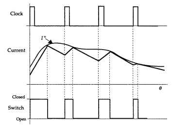
FIGURE 10.86 Clocked turn-on PWM waveforms.
• Acoustic and electromagnetic noise are relatively easy to filter, because the switching frequency is fixed.
• This PWM method has ripple instability that produces subharmonic ripple components for duty cycles above 50 percent (Anunciada and Silva, 1991; Kassakian, Schlecht, and Verghese, 1991). While this instability does not lead to any destructive operating mode, it is a chaotic behavior that reduces performance. The predominant current ripple occurs at half the switching frequency.
• Ripple instability can be eliminated by adding a stabilizing ramp to the reference current (Kassakian, Schlecht, and Verghese, 1991).
Clock Turn-Off PWM. Clocked turn-off PWM is the complement of clocked turn-on PWM. In this method, shown in Fig. 10.87, the clock pulse initiates inductor discharge. Later, when the current decays to I~, a switch closes and the inductance charges until the next clock pulse appears. Once again, the switching frequency is fixed by the clock frequency.
Important aspects of this PWM scheme include the following:
• Current control is not as precise here, since there is no fixed tolerance band that bounds the current.
• The frequency at which switches change state is a fixed design parameter.
• Acoustic and electromagnetic noise are relatively easy to filter, because the switching frequency is fixed.
• This PWM method has ripple instability that produces subharmonic ripple components for duty cycles below 50 percent (Anunciada and Silva, 1991; Kassakian, Schlecht, and Verghese, 1991). While this instability does not lead to any destructive operating mode, it is a chaotic behavior that reduces performance. The predominant current ripple occurs at half the switching frequency.
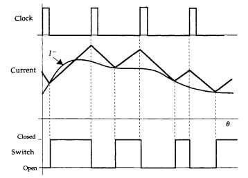
FIGURE 10.87 Clocked turn-off PWM waveforms.
Dual Current-Mode PWM. This PWM method was developed by Anunciada and Silva (1991) to eliminate the ripple instability present in the previous two methods. Their scheme combines the clocked turn-on and clocked turn-off methods in a clever way. For duty cycles below 50 percent, the method implements stable clocked turn-on PWM, whereas for duty cycles above 50 percent, the method implements stable clocked turn-off PWM.
As illustrated in Fig. 10.88, this method has two clock signals, where the turn-off clock is delayed one-half period with respect to the turn-on clock. Operation is determined by logic that initiates inductor charging when the turn-on clock pulse appears or the current reaches I~, and initiates inductor discharge when the turn-off clock appears or the current reaches I+.As shown in Fig. 10.88, the method smoothly moves from one mode to the other. This scheme has all the attributes of the two previous PWM schemes, except for the ripple instability. Furthermore, this scheme reduces to hysteresis PWM if the clock frequency is low compared with the rate at which the inductance charges and discharges.
Triangle PWM. Triangle PWM is a popular voltage PWM scheme that is commonly used to produce a sinusoidal PWM voltage. When used in this way, it is called sinusoidal PWM (Kassakian, Schlecht, and Verghese, 1991).
Application of this scheme to current control is accomplished by letting the PWM input be a function of the difference between the desired current and the actual current.As shown in Fig. 10.89, both the turn-on and turn-off of the switch are determined by the intersections of the triangle waveform and the processed current error. As the processed current error increases, so does the switch duty cycle. Typically, the processed current error is equal to a linear combination of the current error and the integral of the current error (i.e., PI control is used). As a result, as the steady-state error goes to zero, the switch duty cycle will go to the correct value to maintain it there. Though Fig. 10.89 shows a unipolar triangle waveform and error signal, both signals can also be bipolar, in which case zero current error produces a 50 percent duty cycle PWM signal (Murphy and Turnbull, 1988).
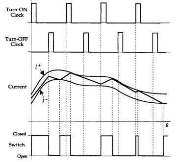
FIGURE 10.88 Dual-current-mode PWM waveforms.
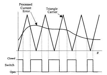
FIGURE 10.89 Triangle PWM waveforms.
Summary. The PWM methods discussed in this section represent the most common methods implemented in practice. Each method has its own strengths and weaknesses; no one PWM scheme is the best choice for every motor drive. Implementation details for these PWM methods are not presented in order to focus attention on the fundamental switching concepts. For reference, conceptual logic diagrams for all the methods are shown in Fig. 10.90. These diagrams apply for positive currents only. When the reference current is bipolar, more complex logic diagrams are required.
Because of the finite switching time of power electronic devices, duty cycles near 0 and near 1 must be avoided in all PWM methods. Switching devices must remain on
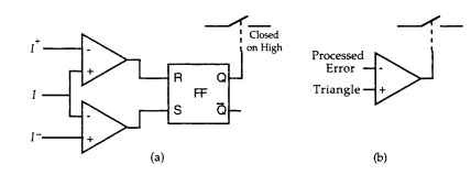
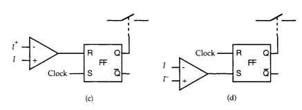
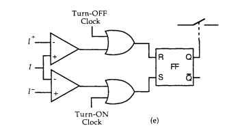
FIGURE 10.90 Conceptual logic PWM implementation: (a) hysteresis PWM, (b) triangle PWM, (c) clocked turn-on PWM, (d) clocked turn-off PWM, and (e) dual-current-mode PWM.
and off for sufficient time to reach equilibrium before being switched back to the opposite state. Sustained operation at either duty cycle extreme increases the loss experienced by the switching devices and can lead to destructive device heating. The choice of PWM frequency is a tradeoff. Generally, the higher the switching frequency, the smaller the current error will be. On the other hand, the higher the switching frequency, the greater the switching loss incurred by the switches. Furthermore, PWM schemes are only as accurate as the current sensors used. Sensor type, placement, shielding, and signal processing are all critical to accurate operation of a current-control PWM method.
PWM Methods (Electric Motors)
Next post: MOTOR DRIVE ELECTRONIC COMMUTATION PATTERNS (Electric Motors)
Previous post: Three-Phase Motors (Electric Motors)
