3.11.9
Ball-bearing systems are preloaded for the following reasons:
• To eliminate radial and axial looseness
• To reduce operating noise by stabilizing the rotating mass
• To control the axial and radial location of the rotating mass and to control movement of this mass due to external force influences
• To reduce the repetitive and non repetitive run out of the rotational axis
• To reduce the possibility of damage due to vibratory loading
• To increase stiffness
Spindle motors and tape guides are examples of applications where preloaded bearings are used to accurately control shaft position when external loads are applied. As the name implies, a preloaded assembly is one in which a bearing load (normally a thrust load) is applied to the system so the bearings are already carrying a load before any external load is applied. There are essentially two ways to preload a ball-bearing system, by using a spring or by using a solid stack of parts.
Spring Preloading. For many applications, one of the simplest and most effective methods of applying a preload is by means of a spring. This can consist of a coil spring or a wavy washer which applies a force against the inner or outer ring of one of the bearings in an assembly.
When a spring is used, it is normally located on the non rotating component; i.e., with shaft rotation, the spring should be located in the housing against the outer rings. Springs can be very effective when differential thermal expansion is a problem. In the spindle assembly shown in Fig. 3.66, when the shaft becomes very hot and
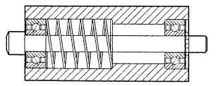
FIGURE 3.66 Spindle assembly using compression coil spring, with shaft rotation.
expands in length, the spring will move the outer ring of the left bearing and thus maintain system preload. Care must be taken to allow for enough spring movement to accommodate the potential shaft expansion.
Since, in a spring, the load is fairly consistent over a wide range of compressed length, the use of a spring for preloading negates the necessity for holding tight location tolerances on machined parts. For example, retaining rings can be used in the spindle assembly, thus saving the cost of locating shoulders, shims, or threaded members.
Normally, a spring preload would not be used where the assembly is required to withstand reversing thrust loads.
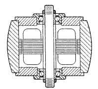
FIGURE 3.67 Rotor outer-ring spacer, with stator mount as inner ring.
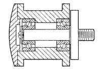
FIGURE 3.68 Typical tape-guide design using screw and washer for solid preloading by clamping inner rings, with outer-ring rotation.
Solid-Stack Preloading. When precise location control is required, as in a precision motor (Fig. 3.67), or a flanged tape guide (Fig. 3.68), a solid preloading system is indicated. A solid-stack “hard” or “rigid” preload can be achieved in a variety of ways. Theoretically, it is possible to preload an assembly by tightening a screw, as shown in Fig. 3.68, or inserting shims, as shown in Fig. 3.69, to obtain the desired rigidity. It should be noted that care must be taken when using a solid-stack preloading system with miniature and instrument bearings. Overload of the bearings must be avoided so that the bearings are not damaged during this process.
Preload Levels. Preloading is an effective means of positioning and controlling stiffness because of the nature of the ball-raceway contact. Under light loads, the ball-raceway contact area is very small, and so the amount of yield or definition is substantial with respect to the amount of load. As the load is increased, the ball-raceway contact area increases in size (the contact is in the shape of an ellipse) and so provides increased stiffness or reduced yield per unit of applied load.
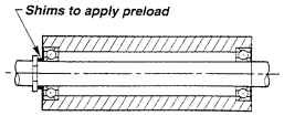
FIGURE 3.69 Shims to apply preload.
This is illustrated in the single-bearing deflection curve shown in Fig. 3.70. When two bearings are preloaded together and subjected to an external thrust load, the axial-yield rate for the pair is drastically reduced because of the preload and the interaction of the forces exerted by the external load and the reactions of the two bearings. As can be seen by the lower curve in Fig. 3.70, the yield rate for the preloaded pair is essentially linear.
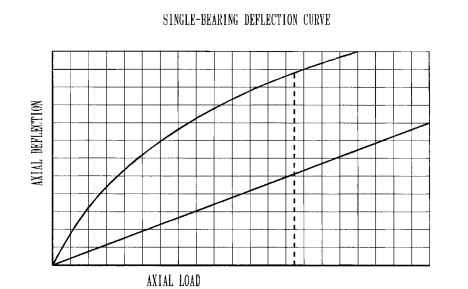
FIGURE 3.70 Single-bearing deflection curve.
Miniature and instrument bearings are typically built to accept light preloads normally ranging from 0.25 lb to not more than 10 lb.
Preloading (Electric Motors)
Next post: SLEEVE BEARINGS (Electric Motors)
Previous post: Assembly and Fitting Procedure (Electric Motors)
