10.8.3
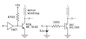
In the preceding circuits, the details of the necessary switches are deliberately ignored. Any switching technology, from toggle switches to power MOSFETS, will work. Figure 10.43 contains some suggestions for implementing each switch, with a motor winding and protection diode included for orientation purposes.
Each of the switches shown in Fig. 10.43 is compatible with a TTL input. The 5-V supply used for the logic, including the 7407 open-collector driver used in the figure, should be well regulated. The motor power, typically between 5 and 24 V, needs only

FIGURE 10.43 Possible switching schemes.
minimal regulation. It is worth noting that these power-switching circuits are appropriate for driving solenoids, dc motors, and other inductive loads as well as for driving stepping motors.
The SK3180 transistor shown in Fig. 10.43 is a power Darlington with a current gain >1000; thus, the 10 mA flowing through the 470-Q bias resistor is more than enough to allow the transistor to switch a few amps of current through the motor winding. The 7407 buffer used to drive the Darlington may be replaced with any high-voltage open-collector chip that can sink at least 10 mA. In the event that the transistor fails, the high-voltage open-collector driver serves to protects the rest of the logic circuitry from the motor power supply.
The IRC IRL540 shown in Fig. 10.43 is a power field-effect transistor. This can handle currents of up to about 20 A, and it breaks down nondestructively at 100 V; as a result, this chip can absorb inductive spikes without protection diodes if it is attached to a large enough heat sink. This transistor has a very fast switching time, so the protection diodes must be comparably fast or bypassed by small capacitors. This is particularly essential with the diodes used to protect the transistor against reverse bias. In the event that the transistor fails, the zener diode and 100-Q resistor protect the TTL circuitry. The 100-Q resistor also acts to somewhat slow the switching times on the transistor.
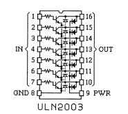
For applications where each motor winding draws under 500 mA, the ULN200x family of Darlington arrays from Allegro Microsystems, also available as the DS200x from National Semiconductor and as the Motorola MC1413 Darlington array, will drive multiple motor windings or other inductive loads directly from logic inputs. Figure 10.44 shows the pinout of the widely available ULN2003 chip, an array of seven Darlington transistors with TTL compatible inputs.
The base resistor on each Darlington transistor is matched to standard bipolar TTL outputs. Each NPN Darlington is wired with its emitter connected to pin 8, intended as a ground pin. Each transistor in this package is protected by two diodes, one shorting the emitter to the collector, protecting against reverse voltages across the transistor, and one connecting the collector to pin 9; if pin 9 is wired to the positive motor supply, this diode will protect the transistor against inductive spikes.
The ULN2803 chip is essentially the same as the ULN2003 chip just described, except that it is in an 18-pin package and contains eight Darlingtons, allowing one chip to be used to drive a pair of common unipolar permanent-magnet or variable-reluctance motors.
For motors drawing under 600 mA per winding, the UDN2547B quad power driver made by Allegro Microsystems will handle all four windings of common

FIGURE 10.44 Pinout diagram of the ULN2003 chip.
unipolar stepping motors. For motors drawing under 300 mA per winding,
Texas Instruments SN7541, 7542 and
7543 dual power drivers are a good choice. Both of these alternatives include some logic with the power drivers.
Practical Unipolar and Variable-Reluctance Drivers (Electric Motors)
Next post: Bipolar Motors and H Bridges (Electric Motors)
Previous post: Unipolar PM and Hybrid Motors (Electric Motors)
