4.9.6
The polarity of the armature becomes obvious with the winding of the second coil, as shown in Figs. 4.116 and 4.117.
Tracing the path of current flow away from the positive brush in Fig. 4.116, through the active coil 2 to 7, the direction through the coil sides within the coil com-mutated by the positive brush is away from the commutator.
Figure 4.117 shows the opposite current direction.Therefore,the armature of Fig. 4.117 will run in the opposite direction from that of Fig. 4.116.
Note that this discussion is in terms of a steady dc condition. However, the relationship still exists for any instantaneous condition of ac motors. Thus, the same method of analysis is used in both ac and dc universal motors.
Figures 4.118 and 4.119 show each armature wind continued to the point of the first overlap. Note in Fig. 4.118 that two coil sides appear in slot 6, while in Fig. 4.119, two coil sides appear in slot 1.
Figures 4.120 and 4.121 show the addition of coil 7 to 12 (12 to 7 progressive), which coil is opposite the commutated coil 1 to 6. The coil 7 to 12 is commutated by the negative brush while the coil 1 to 6 is commutated by the positive brush.
Figure 4.122 shows the continuance of wind to the first double-overlap coil 8 to 1. Also, Fig. 4.123 shows the first double-overlap coil 11 to 6 in place.
Figures 4.124 and 4.125 show the wind completed.
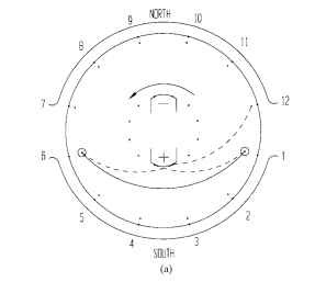
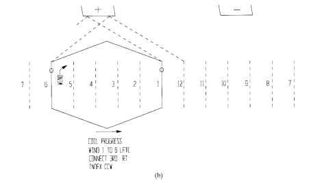
FIGURE 4.115 Armature lap winding, first coil progresses: (a) end view, and (b) side view.
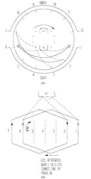
FIGURE 4.116 Armature lap winding, second coil retrogresses: (a) end view, and (b) side view. Polarity and connection pattern are now indicated.
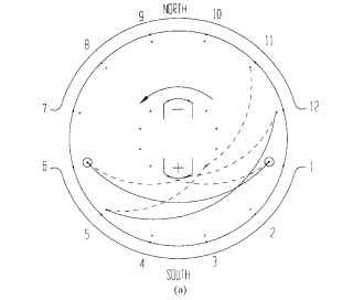
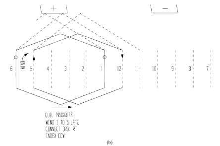
FIGURE 4.117 Armature lap winding, second coil progresses: (a) end view, and (b) side view. Polarity and connection pattern are now indicated.
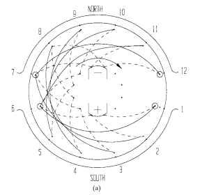
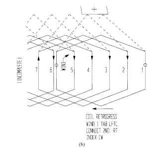
FIGURE 4.118 Armature lap winding, first overlap, coil retrogresses: (a) end view, and (b) side view.
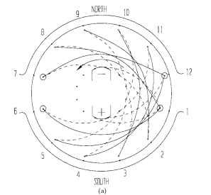
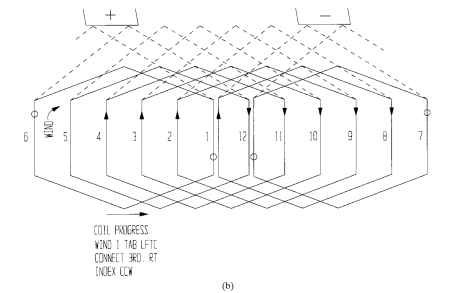
FIGURE 4.119 Armature lap winding, first overlap, coil progresses: (a) end view, and (b) side view.
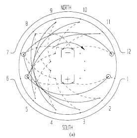
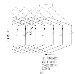
FIGURE 4.120 Armature lap winding, second commutat-ing coil retrogresses: (a) end view, and (b) side view.
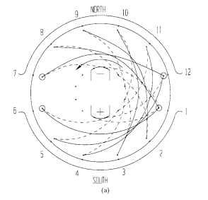
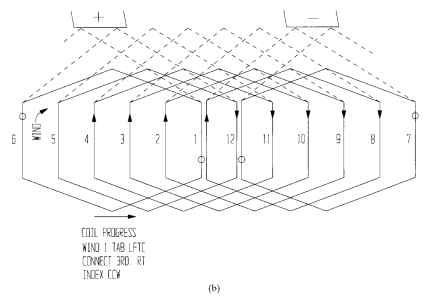
FIGURE 4.121 Armature lap winding, second commutating coil progresses: (a) end view, and (b) side view.
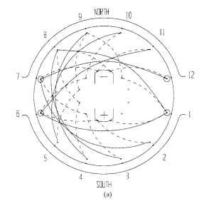
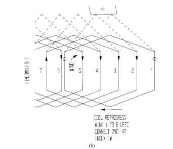
FIGURE 4.122 Armature lap winding, first double overlap, coil retrogresses: (a) end view, and (b) side view.
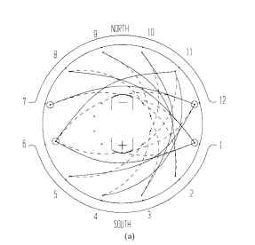
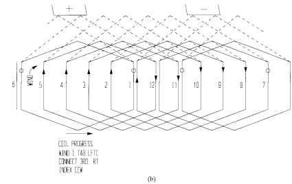
FIGURE 4.123 Armature lap winding, first double overlap, coil progresses: (a) end view, and (b) side view.
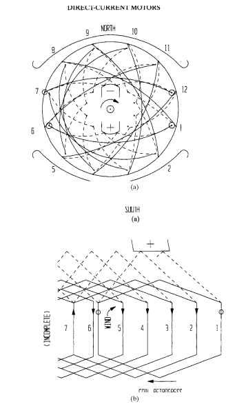
FIGURE 4.124 Armature lap winding, completed progressive wind, coil retrogresses: (a) end view, and (b) side view.
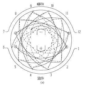
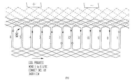
FIGURE 4.125 Armature lap winding, completed progressive wind, coil progresses: (a) end view, and (b) side view.
Armature Polarity (Electric Motors)
Next post: Anchored Lead Loops (Electric Motors)
Previous post: Winding Specifications (Electric Motors)
