4.2.3
In order to determine the resistance of the armature as seen by the brushes, the following parameters need to be set:

The length of one turn in the winding must be determined. There are three different methods of determining the length of a turn.
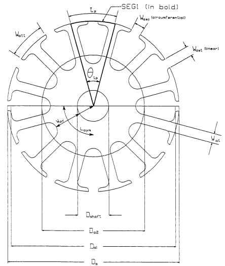
Armature End-Turn Length—Method 1. This method uses the geometry of the lamination to estimate the average end-turn length. The accuracy of this method is

FIGURE 4.54 Armature lamination slot.
dependent on the capabilities of the winding machinery. Using geometry and the width of the armature yoke for a magnetic shaft, the mean end-turn length is found by averaging the distances around the lamination at the radii of the top of the slot and the bottom of the slot. The mean end-turn length of one side of one turn, in inches, is
![]()
In order to understand the other methods of determining end turn length, the formulas for armature resistance are discussed first.
Armature Resistance. The mean turn length is the sum of the mean end-turn length for each of two ends plus twice the stack length, in feet (because wire resistances are given in ohms per foot):

where pa is the armature wire resistance per foot and Fwsa is the armature winding stretch factor, usually 1.02 to 1.10.
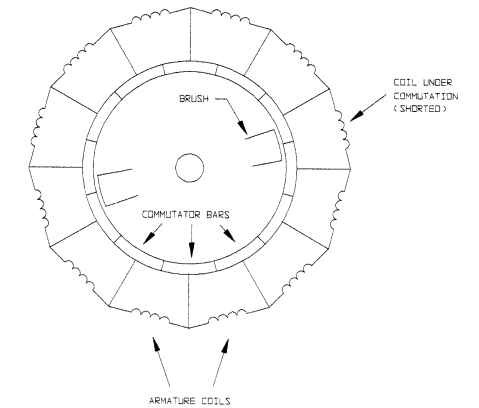
The number of coils to be considered for armature resistance depends on the number of commutating coils, so the number of active coils for the armature is

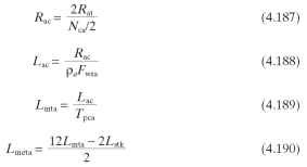
Armature End-Turn Length—Method 2. This method assumes that you already have a motor and know ,Rat, Tpca, Fwsa, and pa. From this, the Lmeta can be calculated and then used for calculations for other motors with the same lamination. The following four formulas determine the mean end-turn length for one end of one turn.

Armature End-Turn Length—Method 3. Measure what looks like the average end turn on an existing motor.
Armature Slot Fill. The maximum armature slot fill depends on the winding equipment. A full slot could be anywhere from 40 to 55 percent. The slot fill is calculated by assuming that the wires are lying side by side as if they were square. Using

FIGURE 4.55 Schematic of armature current paths.
the outside diameter of the armature wire as Daw (this depends on insulation thickness), the percentage of armature slot fill is
![]()
Armature Copper Weight. Using pound-feet from the wire tables, the weight of the armature copper Wtac, is:
![]()
![]()
![]()

Assuming that the copper in the end turns effectively distributes the total copper weight over a solid cylinder, the inertia of the copper in the armature Jac, oz • in • s2,is
![]()
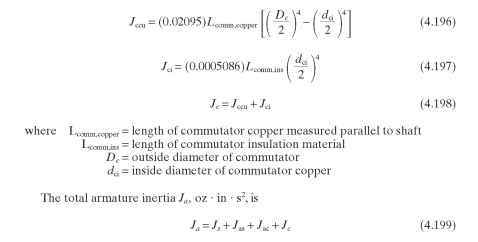
The inertia of the commutator is split into the inertia of the copper bars and the insulation on the inside (see Fig. 4.69 in Sec. 4.3.2). The commutator inertia Jc, oz • in • s2,is

Armature Balance. ISO Standard 1941 gives guidelines for acceptable balance and vibration limits for electric machines based on their usage. In general, the lower the unbalance, the longer the motor life. Unbalance affects bearing wear by causing the shaft to pound against the bearing, breaking down the surface and pumping out the lubricant. It affects brush life adversely by causing the brushes to instantaneously lose contact with the commutator surface, resulting in electrical arcing, wear, and higher levels of EMI. If this occurs near a resonant speed, the condition becomes severe and the motor instantaneously ceases operation because the brush lifts completely away from the commutator, causing an open circuit.
Armatures should be aligned in the magnetic field such that there is a net magnetic force pulling the armature toward the commutator end of the motor. This reduces end bounce and improves brush life.
Armature Conductors (Electric Motors)
Next post: Field (Stator) (Electric Motors)
Previous post: Magnetic Circuits (Electric Motors)
