An intermediate source form is an internal form of a program created by the compiler while translating the program from a high-level language to assembly-level or machine-level code. There are a number of advantages to using intermediate source forms. An intermediate source form, represents a more attractive form of target code than does assembly or machine code. For example, machine idiosyncrasies, such as requiring certain operands to be in even- or odd-numbered registers, can be ignored. Also, bookkeeping tasks, such as keeping track of operand stacks, can be avoided.
Certain optimization strategies can be more easily performed on intermediate source forms than on either the original program or the assembly-level or machine-level code. For example, optimizations which depend on flow analysis, such as register allocation (see Sec. 13-2), are facilitated by the use of an intermediate source form.
An intermediate source form is useful when both a checkout "compiler" and an optimizing compiler are produced for the same programming language. Intermediate code is produced for both compilers. An intermediate-code interpreter is written for the checkout version. This interpreter can be used to produce meaningful run-time error diagnostics and traces that are difficult to produce when executing object modules. The optimizing compiler performs optimizations on the intermediate source form and produces an object module.
Compilers which produce a machine-independent intermediate source form are more portable than those which do not. The intermediate source form can be run on a machine by writing a corresponding macro in the assembly language of the machine for each instruction of the intermediate source language. This advantage is especially true of threaded code and pseudo machine, code.
The major disadvantage of using an intermediate language is that code produced can be less efficient than producing machine-level code directly. Obviously the reason why this is argued is that an intermediate language necessitates another level of translation (i.e., from the intermediate source form to the machine-level code). However, the types of optimization that can be performed because an intermediate language is used can more than offset the apparent inefficiency of a two-step translation. This aspect will become clearer in Chaps. 12 and 13 when we discuss optimization.
In this topic, we discuss five types of intermediate source forms: Polish notation, n-tuple notation, abstract syntax trees, threaded code, and pseudo or abstract machine code. We devote one section to each of these types.
POLISH NOTATION
Suffix or reverse Polish notation was one of the earliest intermediate source forms developed and remains among the most popular. It has been used in some FORTRAN compilers as an intermediate form for arithmetic expressions. It has also been used in some interpreters, such as Hewlett Packard’s interpreter for BASIC. We introduced suffix Polish notation as a method of specifying arithmetic expressions unambiguously without recourse to parentheses. In this section, we demonstrate how Polish notation can be used as an intermediate source form not only for arithmetic expressions but also for other language constructs.
In Sec. 7-1.2, we presented Algorithm REVERSE_POLISH for converting infix expressions into their suffix Polish equivalents. This algorithm works well for expressions such as A + B which have binary operators but does not handle expressions such as —A which have unary operators. Unary operators can be handled by making allowance for the type of the operator when removing operands from the stack, or by converting unary operations into binary ones. For example, —A could be represented as 0 – A and then handled as a binary operation.
An algorithm to translate the Polish intermediate source form of an arithmetic expression into a simple machine language can easily be written. Algorithm ASSEMBLY_CODE, which is presented later in Sec. 13-2, is an example of such an algorithm.
When Polish notation is extended to include nonarithmetic language constructs, the more powerful notation which results is often called extended reverse Polish notation (henceforth referred to as extended Polish). For example, operators can be added to handle the assignment operation, conditional branching, and subscripted variables. To illustrate this, let us examine how Polish notation can be extended to include conditional branching.
Consider an if statement with the following format:
This statement cannot be represented in Polish as
because both (stmtj) and (stmt2) would be evaluated before being placed on the stack. Since the purpose of the if statement is to perform only one of (stmt!) and (stmt2>, a different representation must be adopted. Writing the statement as
solves this problem by introducing the more primitive constructs of BZ and BR. BZ is a binary operator that causes a branch to (labelj), which is the first symbol of (stmt 2), if (expr) evaluates to zero {false). BR is a unary operator that causes a branch to (label2), which is the symbol immediately following the last symbol of (stmt2). Both branching operators clear the stack of their operands but do not add any result to the top of the stack.
As a second example of extending Polish notation to nonarithmetic operators, let us look at how subscripted variables, which indicate array references, are handled. In extended Polish, the string
MY_ARRAY ARRAY_REF
can be evaluated to determine the address of array element MY_ARRAY[7,5,10]. ARRAY_REF is the array-reference operator. It determines the number of dimensions of the array, in this case MY_ARRAY, and pops this many operands off the evaluation stack. The address of the array element is then calculated using these operands, and information about array bounds is obtained from the symbol table.
Some compiler writers have used prefix Polish notation as an intermediate form of source code. Topic 14 will describe a system that uses this form of notation.
A Polish string is not very convenient for optimization purposes. It is therefore desirable to transform a Polish string to other more suitable forms. The next two sections describe these forms.
We have presented a small number of examples of how Polish notation can be extended to nonarithmetic operations. The exercises aid the reader in examining how some other language constructs can also be represented in extended Polish.
V-TUPLE NOTATION
N-tuple notation is an intermediate source form in which each instruction consists of n fields. Usually, the first field specifies an operator and the remaining n — 1 fields can be used as operands. This standardized format of n-tuple notation allows for easy translation into code for register machines because the operands are often specified as the result of some previous operation. In this section, we examine the two most popular forms of n-tuple notation, triples and quadruples, which are the source forms corresponding to values for n of 3 and 4, respectively.
Triple notation is a type of n-tuple notation in which each instruction has three.fields. Consider the arithmetic expression Y + Z. The three parts of this binary operation are the operator ( + ) and the two operands ( Y and Z). Triple notation is ideal for representing a binary operation by using the following format:
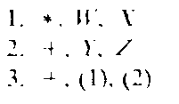
The expression W* X + (Y + Z) is represented in triple notation as follows:
Each triple is numbered, and the result of a previous triple is specified by its number in parentheses. Thus the (1) and (2) which appear in triple 3 specify that the results of triple 1 and triple 2 are to be used as operands. The conditional statement
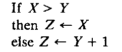
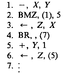
can be represented in triple notation as follows:
The BMZ and BR operators specify branch on minus or zero and unconditional branch, respectively. The second field of these instructions gives the value, if any, to be tested for the condition, and the third field gives the number of the triple which is the destination of the branch.
Performing code optimization on triples can be difficult. As will be shown later, code optimization often involves the movement of code, but triples cannot be moved without changing all references to affected triples. For example, if triple 4 is moved after triple 7, triples 4, 5, 6, and 7 must all be renumbered. Of course, all references to these triples must also be adjusted. As a result, simple triples are not a particularly good intermediate source form when optimization is to be performed.
Indirect triples can be used instead of triples. A separate table which gives the order of execution for the triples is used. When optimization is performed, the order of the entries in this table is changed; the actual triples are left alone. If two triples are identical, one can be deleted from the triple table. This optimization must be performed carefully, however, since only one temporary variable is ordinarily associated with each triple. The following example statements
can be represented by indirect triples as follows:
|
Operations |
Triples |
|
1. (1) |
|
|
2. (2) |
|
|
3. (3) |
|
|
4. (4) |
|
|
5. (1) |
|
|
6. (5) |
Quadruple notation is another type of n-tuple notation in which each instruction has four fields of the form:
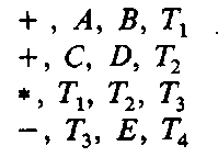
where (operand^ and (operand2> denote the first and second operand, respectively, and (result) specifies the result of the operation. The result is usually a temporary variable. Such a variable may be assigned to either a register or main memory location later on by the compiler. For example, the expression (A + B)*(C + D) – E can be represented by the following sequence of quadruples:
where 7\, T2, T3, and TA are temporary variables.
Quadruples facilitate the performance of several program optimizations. One drawback of using quadruples is that the allocation of temporary names must be managed. Such a management strategy will reuse some temporaries.
Quadruples will be used extensively in the optimization topics.
ABSTRACT SYNTAX TREES
A parse tree is another popular intermediate form of source code. Because a tree structure can be easily restructured, it is a suitable intermediate form for optimization compilers. A parse tree can be stripped of unnecessary information to produce a more efficient representation of the source program. Such a trans- formed parse tree is sometimes called an abstract syntax tree.
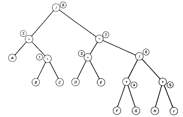
Figure 10-1 Example of an abstract syntax tree.
In this type of tree each nonleaf and leaf node represents an .operator and variable name, respectively. For example, the expression
can be represented by the abstract syntax tree in Fig. 10-1. In the tree structure, the circled numbers indicate the order in which the tree nodes are created by a bottom-up parser. Observe that each nonleaf node has a left and right direct descendent which is either a variable name (leaf) or a nonleaf node.
The traversal of an abstract syntax tree can yield the Polish notation forms introduced earlier. The preorder and postorder traversals of the tree given in Fig. 10-1, for example, yield the prefix and suffix Polish form of the given expression, respectively:
These Polish strings are linear representations of the syntax tree.
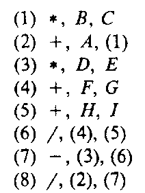
Also the triples that represent an expression can be viewed as a direct representation of a syntax tree. The following set of triples correspond to the tree given in Fig. 10-1:
with the last triple being associated with the root node of the tree. Note that each triple represents a subtree. The operator in a triple corresponds to the root of a subtree. Each operand is either a variable name (a leaf) or a triple number (a sub-subtree). With this interpretation, the circled numbers in Fig. 10-1 directly correspond to the triple numbers.
Variants of abstract syntax trees have been used as an intermediate form of source code in several compilers. In Chap. 14 we examine one form of abstract syntax tree called TCOL which is used in a compiler-compiler system.
THREADED CODE
This section describes an intermediate form of source code which is amenable to machine-independent implementation. Threaded code is included because of its semi-interpreted nature. We first introduce the notion of direct threaded code and then present indirect threaded code. The ideas in both approaches are illustrated using PDP-11 code.
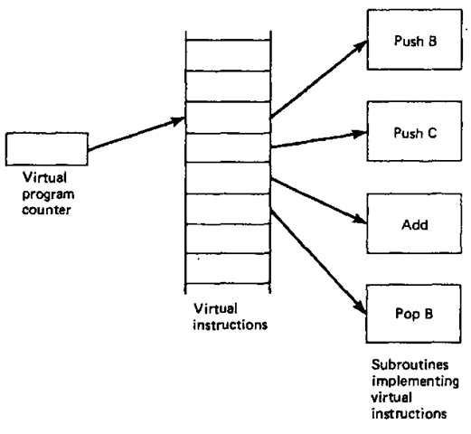
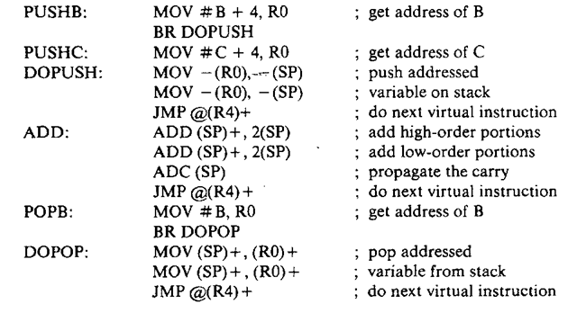
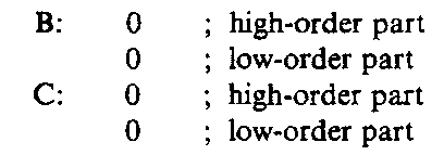
Direct threaded code (Bell, 1973) concerns generating code that consists of a linear list of addresses for routines which are to be executed. Some routines are program-specific and deal with operand access; these must be generated by the compiler. Other routines are standard library routines. Figure 10-2 illustrates the model for a direct-threaded-code system.
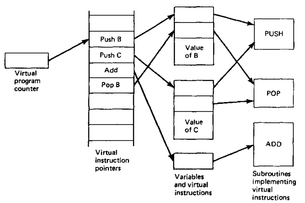
Indirect threaded code (Dewar, 1975) introduces a level of indirection to the model given in Fig. 10-2. Instead of having a linear list of addresses of routines, indirect threaded code has a linear list of addresses of words which in turn contain the addresses of the routines to be executed. The model which incorporates this level of indirection is exhibited in Fig. 10-3.
The comparison of the two threaded-code models indicates that the indirect-threaded-code model involves only the manipulation of addresses and not the generation of code. Indirect threaded code often can be generated in an essentially machine-independent manner. On the other hand, direct threaded code contains operand access routines. Machine independence in this case is more difficult to achieve.
Figure 10-2 A model for direct threaded code.
Both threaded-code models will be exhibited using PDP-11 code. The PDP-11 (see Sec. 13-3.1) has eight (16-bit) general registers: R0-R5, SP, and PC. The registers R0-R5 are of a general-purpose nature. SP serves as a hardware stack pointer where (SP) + is an addressing mode which pops the stack, – (SP) is an addressing mode which pushes the stack, and PC is a hardware program counter.
In the direct-threaded-code model (see Fig. 10-2) the virtual program counter is denoted by register R4. Each routine which implements a virtual instruction passes control to the next operation by means of the following instruction:
which indicates a jump to the routine whose address is contained in the virtual instruction.
Figure 10-3 A model for indirect threaded code.
The address of the virtual instruction is contained in R4. At the same time, R4 is incremented to point to the next virtual instruction.
The virtual-instruction list for the direct-threaded-code evaluation of the statement![]() is
is
The routines implementing the virtual instructions are as follows:
The code for the storage of variables is the following:
In the indirect-threaded-code model (see Fig. 10-3) the virtual program counter is also register R4. The register, however, contains the address of an address of an address of a routine implementing a virtual instruction. Each routine which executes a virtual instruction passes control to the next virtual instruction by the instruction pair:
which places the address of the address of the current virtual instruction in RO while incrementing R4. The address in RO is then used to invoke the next virtual instruction.
The virtual-instruction list for the indirect-threaded-code evaluation of the statement![]() is
is
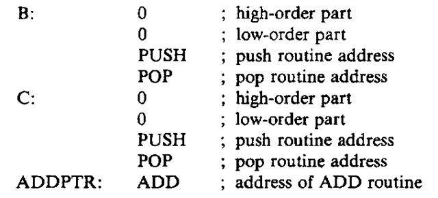
The routines implementing the virtual instructions are as follows:
The code for the storage of variables is the following:
Note that because of the peculiarities of addressing on the PDP-11 the values of variables have been placed at the beginning of a block as indicated in Fig. 10-3.
The concept of threaded code has general applicability to code generation for several languages. In particular, a machine-independent version of SPITBOL (Dewar, 1971), which is based on the technique of indirect threaded code, has been developed.
