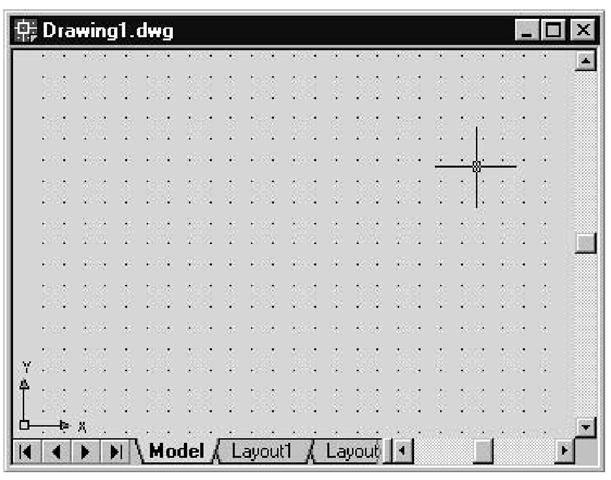
A grid is a net of regularly spaced dots that together provide a visual cue in the drawing area, making it easier to position points defining lines or other drawing components in the Model Space (see Figure 8.4). You can define boundary limits for the grid, as well as control the horizontal and vertical distances between points on the grid.
Displaying Grid Points
To display the grid from the AutoCAD window, simply click the GRID button in the status bar found along the bottom boundary of the AutoCAD window. A pattern of dots should appear in the drawing area to represent grid points.
If this doesn’t happen, you’ll probably get an error message in the command line. You’ll see how to overcome this in the next few sections, but sometimes repeatedly executing the View – Zoom – In command will eventually display the grid points.
Figure 8.4 Grid points in the drawing area
Displaying Grid Points from a Macro
The GridOn property of the Viewport object controls whether or not grid points are displayed. When GridOn is set to True, the points are displayed at intervals dictated by the current Grid Spacing setting—just as if you’d clicked the GRID button. The following ShowGrid macro demonstrates how this property is set in code to display grid points from a macro. I’ve started a new project and placed the ShowGrid macro into the ThisDrawing Code window.
Notice how the ActiveViewport property has to be reassigned to NewViewport, which is a reference to itself, in order to toggle the grid on or off. Using the Regen method (see next section) doesn’t have any effect because it doesn’t reset the active viewport.
The Active Viewport
A viewport is a rectangular area that displays all or part of a drawing from the Model Space. The viewport definition is stored in the Viewport object. The Viewports collection contains all the Viewport objects associated with a drawing. Although several viewports can be visible at the same time, only one viewport can be designated as the active one—this is referenced by the ActiveViewport property of the current drawing document:
If you update any of the properties in a viewport, you must regenerate it using the Regen method of the ThisDrawing object in order for your changes to be reflected in the Model Space. This is achieved by passing to the Regen method the viewports that have changed:
Two AutoCAD constants can be used for the argument: acActiveViewport to regenerate only the objects associated with the active viewport, and acAllViewports to regenerate the entire drawing. Regenerating a viewport involves recalculating the screen coordinates and view resolution of all objects associated with that viewport.
Setting Grid Limits
You can set the boundaries that enclose the grid in the drawing area, which can serve as a useful guide while you are drawing. The following steps show you how this is done from the AutoCAD window:
1. Choose Format + Drawing Limits. The command line will prompt you to specify the coordinates of the lower-left corner of the grid and gives their current setting as 0,0.
2. Press Enter to accept the current setting. The command line changes to a prompt for the upper-right corner limit.
3. Type 25,25 and press Enter. The grid expands to the edge of the drawing area. (If these values are too large for your drawing, go ahead and make them smaller.)
Setting Grid Limits from a Macro
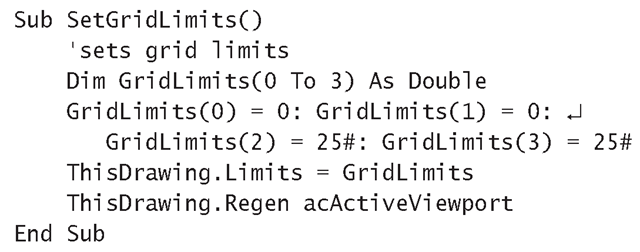
Grid limits can be set from a macro using the Limits property of the current drawing document, as shown in the following SetGridLimits macro. The Limits property is set to a four-element array containing the positions of two diagonally opposite corner points of the rectangular area that will contain the grid. In the macro, the two corners defining the grid limits are (0,0) and (25,25). The first two elements define the x- and y-coordinates of the bottom-left corner of the boundary, and the last two elements define the top-right corner. To try it out, add the SetGridLimits macro to the same project that contains ShowGrid.
The Limits property not only determines the area that the grid will cover but also what will be displayed when the ZoomAll method is called.
You can also find out what the grid limits are by setting up a Variant-type variable and assigning to it the value returned by the Limits property. For example:
The coordinates defining the corners can then be accessed as if CurrentLimits variable were a four-element array.
Displaying the Whole Grid
The Zoom All command on the View menu displays the entire area defined by the Limits property settings. Simply choose View + Zoom + All from the AutoCAD window, and the whole grid will be displayed fitting snugly inside the Model Space area.
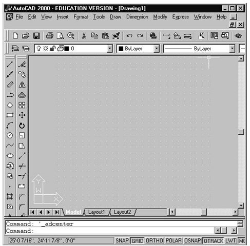
In Figure 8.5, the status bar reflects the position of the crosshairs cursor at the top-right grid point after running the SetGridLimits macro. The cursor’s x- and y-coordi-nates are shown in the status bar as roughly (25′, 25′).
The View –Zoom- All command preserves the shape of a grid rather than extending it over the whole Model Space.
Figure 8.5 Grid after using View – Zoom – All
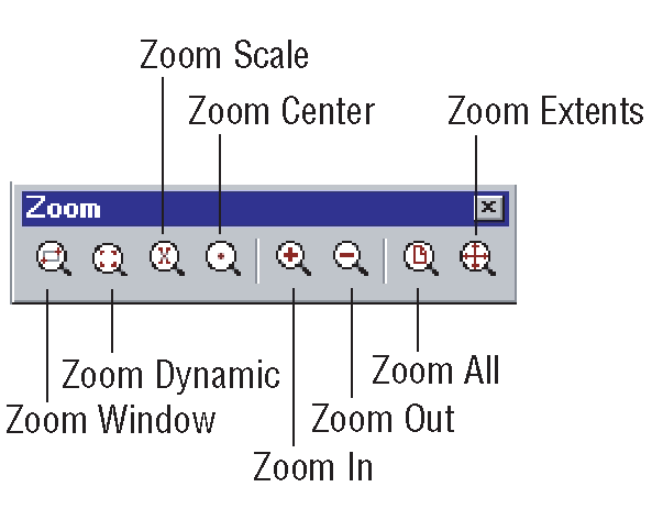
Zoom Toolbar
VBA has an entire toolbar dedicated to zooming.
Displaying the Whole Grid from a Macro
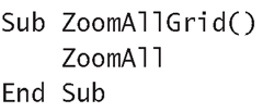
The ZoomAll method allows you to see the entire grid in the Model Space—why not add it to your ShowGrid project, too?
If the message "Grid too dense to display" appears in the command line when you run the ZoomAll macro, the grid points are too close together to display them all. You can solve this problem by repeatedly executing View + Zoom + In. Eventually you will be able to see part of the grid. If you need to view the whole grid area, change the spacing settings so that fewer grid points are required (see next section).
Setting the Spacing for Grid Points
The default spacing between grid points for Architectural drawing units is 1/2". If your drawing grows to, say, 25 feet square (like our floor plan), that means 600×600 grid points—approximately one point per screen pixel. If all these points were drawn, the grid would end up as a rectangle filled with solid color. When grid points are displayed too close together, it defeats the purpose of having them in the first place; it becomes virtually impossible to select one point without also selecting its neighbors. For this reason, AutoCAD won’t display grid points unless they are spaced at a reasonable distance.
If the spacing between grid points is too small, AutoCAD displays the error message "Grid Too Dense To Display," and no grid points are displayed.
When you set the distance between grid points, consider the amount of accuracy you need for your drawing. In the floor plan you’re about to develop, accuracy to one foot is probably more than adequate—this gives you a grid of 25×25 points.
To adjust the spacing between grid points:
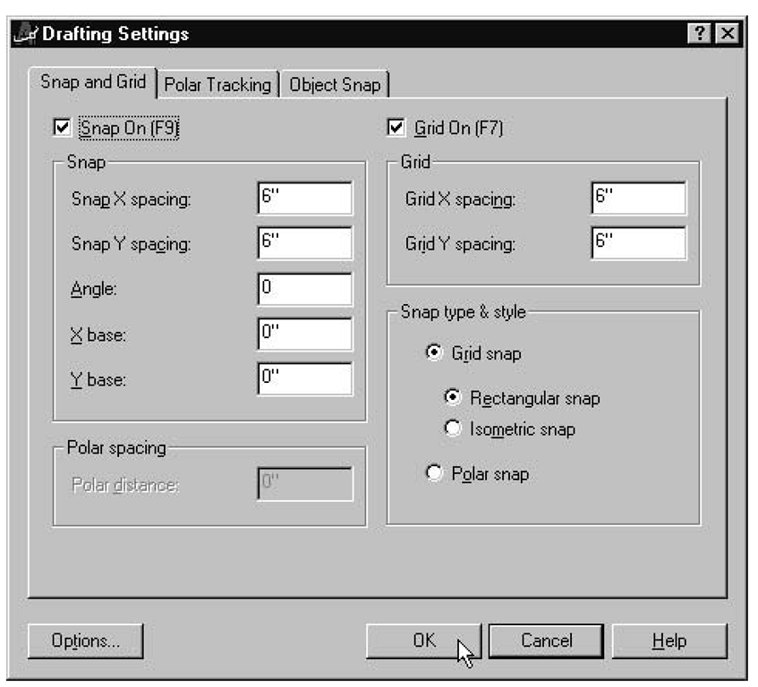
1. Choose Tools – Drafting Settings. The Drafting Settings dialog box appears (Figure 8.6).
2. Type 12 to replace the default 6 in the GridX Spacing text box; do the same for the GridY Spacing value. (You don’t need to type the " symbol for inches because this is the default.) The drawing space now contains a grid of 25×25 dots.
Figure 8.6 Use the Drafting Settings dialog box to set grid-point spacing
The inch symbol (") is not required when entering a value for GridX Spacing and GridYSpacing in the Drafting Settings dialog box; inches is the default unit. However, for settings in feet, you always have to enter the foot symbol ().
Setting the Spacing for Grid Points from a Macro
The SetGridSpacing method sets the grid spacing in the active viewport. This method requires two arguments—the horizontal and vertical spacing increments. The Adjust-GridSpacing macro given here sets the spacing to 12" in both directions before reactivating the viewport to display the grid points with their new spacing. To try the AdjustGridSpacng macro, add it to your ShowGrid macro project.
