3.3
3.3.1
Talker echo, listener echo
The most important echo is talker echo, the perception by the talker of his own voice but delayed. It can be caused by electric (hybrid) echo or acoustic echo picked up at the listener side.
If talker echo is reflected twice it can also affect the listener. In this unusual case the listener hears the talker’s voice twice: a loud signal first, and then attenuated and much delayed. This is listener echo.
These two types of echo are illustrated on Figure 3.4.
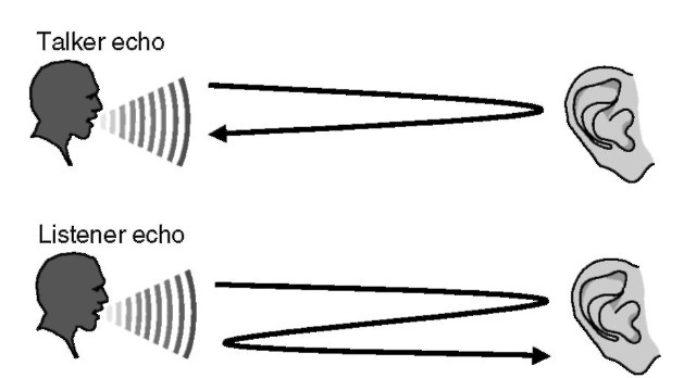
Figure 3.4 Talker and listener echo.
3.3.2
Electric echo
3.3.2.1
What is a hybrid?
The simplest telephone system would look like Figure 3.5. However, to use fewer wires, the phone system was designed to use just two wires. The first 2-wire phones looked like Figure 3.6. Because of parasitic capacities on the line, most microphone signals were dissipated in the talker s loudspeaker (who then tended to speak lower), and almost nothing reached the listener.
The final design arrived at is as shown on Figure 3.7, where Zref matches the characteristic impedance of the line. Now, the microphone signal is split equally between Zref and the line, and the speaker hardly hears himself in his own loudspeaker (a small unbalance is kept for him not to have the impression that he is talking in the air). In the ETSI standard Zref is a 270-£2 resistor connected to a 750-£2 resistor in parallel with a 150-nF capacitor. In France, for instance, Zref is a 150-nF capacitor in parallel with a 880-££ resistor, wired to a 210-££ resistor (complex impedance), but some older phones are also equipped with a real impedance of 600 ££.
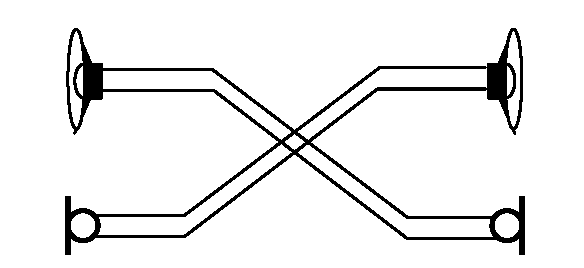
Figure 3.5 Simplest phone network.
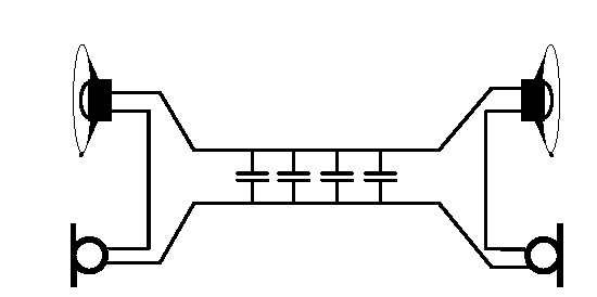
Figure 3.6 Basic phone connection over a single pair.
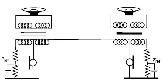
Figure 3.7 Improved design using a hybrid.
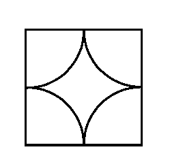
Figure 3.8 Hybrid symbol.
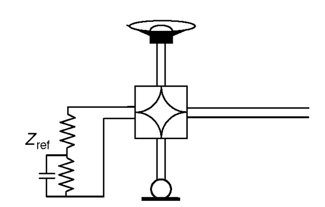
Figure 3.9 Simplified representation of an analog phone.
These values were found to be a good average for a typical line. The actual impedance of a given line will vary according to its length (between 0 km and 9 km, typically), so there is always some mismatch.
The common way to symbolize this impedance adaptation device is illustrated in Figure 3.8, where each corner represents 2 wires. It is called a duplexer, or a hybrid. Each half of the circuit of Figure 3.7 can be represented as in Figure 3.9. A hybrid can be integrated easily, a possible circuit is shown in Figure 3.10.
The hybrid is also commonly used in an analog telephone network to allow line signal amplification using the configuration of Figure 3.11.
3.3.2.2
Electric echo
In Figure 3.7 or Figure 3.11, Zref never matches exactly the characteristic impedance of the 2-wire line, so a portion of the incoming signal is fed back in the outgoing signal. This parasitic signal is the hybrid echo and has all sorts of consequences:
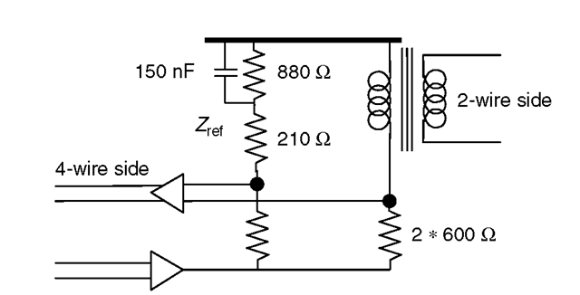
Figure 3.10 Emulating a hybrid with operational amplifiers.

Figure 3.11 Line amplification in the 4-wire path.
• For instance, in Figure 3.11 the signals will loop between the two amplifiers and generate a ‘cathedral effect if the one-way delay is about 20 ms. To avoid instability in the network, a loss of 6 dB at least is introduced in the 4-wire path.
• The talker at the other end of the line will hear himself after a round trip delay (talker echo).
In many countries, the transit network is entirely built using 4 wires (any digital link is a virtual 4-wire link). Two- to 4-wire separation occurs at the local switch where the analog phone is connected. Because the echo generated at the switch end comes back to the phone undelayed, it has no effect. On the other hand, the echo generated at the phone end travels back to the other phone through the network (Figure 3.12) and is noticed as soon as the round trip time is above 50 ms (without echo cancelation in the 4-wire path). ITU Recommendation G.165 provides more details on the handling of hybrid echo.
3.3.3
Acoustic echo
Note: In the following text we will term ‘loudspeaker phone’ an amplified phone without acoustic echo cancelation and ‘hands-free phone’ as amplified phone with acoustic echo cancelation.
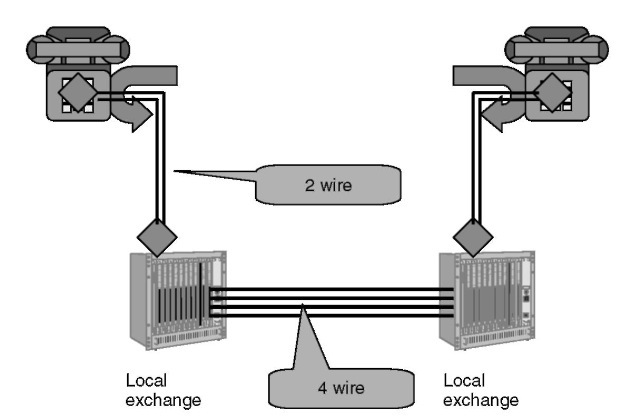
Figure 3.12 Hybrid echo.
Acoustic echo is simply that part of the acoustic signal that is fed back from the loudspeaker of a device to the microphone of that same device. Typically, acoustic echo is a parasitic signal about 10-15 dB (in the case of a loudspeaker phone) below the acoustic signal of the person actually talking into the microphone. Just like hybrid echo, such a level of acoustic echo goes unnoticed if the round trip delay is below 50 ms. After 50 ms the person at the other end of the line gets the impression of talking inside a deep well and then begins to distinctly perceive the echo of his own voice.
An easy way to suppress acoustic echo is to use a headset. However, with appropriate echo-canceling devices it is possible to reduce the power of parasitic echo to about 45 dB below the speaker’s signal, even using a loudspeaker phone.
ITU recommendations G.161, G.167, and P.330 focus on acoustic echo and give some values for the typical echo path to use during the testing of echo cancelers:
‘• for teleconference systems, the reverberation time [time after which the sound energy of an impulse has decayed below 60 dB of the original power] averaged over the transmission bandwidth shall be typically 400 ms. The reverberation time in the highest octave shall be no more than twice this average; the reverberation time in the highest octave shall be no less than half this value. The volume of the typical test room shall be of the order of 90 m3.’
‘• for hands free telephones and videophones, the reverberation time averaged over the transmission bandwidth shall be typically 500 ms; the reverberation time in the highest octave shall be no more than twice this average; the reverberation time in the highest octave shall be no less than half this value. The volume of the typical test room shall be of the order of 50 m3.’
‘• for mobile radio telephones an enclosure simulating the interior of a car can be used.[...] A typical average reverberation time is 60 ms. The volume of the test room
shall be 2.5 m3.’
Echo cancelers usually do not work as well with acoustic echo as with electric echo, because the acoustic echo path varies much more, which makes it more difficult to dynamically adapt the synthesized echo to the real one. In particular, echo cancelers compliant with ITU recommendations G.165 performance are likely to be insufficient. Even the newer recommendation, G.168, already implemented by most vendors, may not be sufficient in some cases. Both recommendations also provide the ability to stop echo cancelation when detecting the phase reversal tone of high-speed modems. Typical values for acoustic echo attenuation in current devices are:
• Loudspeaker phones (80% of the market): 10-15 dB.
• Hands-free phones: 35-40 dB.
• Phones with good-quality handsets: 35-40 dB.
3.3.4
How to limit echo
Two types of devices are commonly used to limit echo: echo cancelers and echo suppressors. Electric and acoustic echo reduction is measured in the 4-wire path with the reference points indicated in Figure 3.13.
3.3.4.1
Echo suppressors
Echo suppressors were introduced in the 1970s. The idea is to introduce a large loss in the send path when the distant party is talking. This technique is widely used in low-end hands-free phones, but tends to attenuate the talker when the distant party talks at the same time. It is very noticeable because the background noise that was perceived over the talker s voice by the listener suddenly disappears when he stops speaking or when the listener starts talking. It sometimes creates the impression that the line has been cut, prompting the response: ‘Are you still there?’
3.3.4.2
Echo cancelers
The echo canceler functional model is shown in Figure 3.14. An echo canceler is much more complex than an echo suppressor, because it actually builds an estimate of the shape
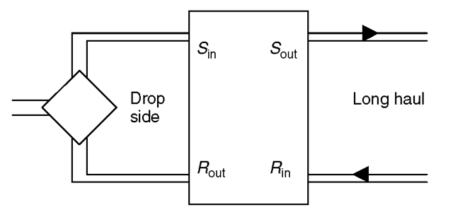
Figure 3.13 Reference points for echo measurement.
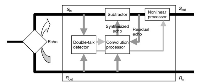
Figure 3.14 Echo canceler block diagram.
of the echo to remove it from the incoming signal. The echo is modeled as a sum of signals similar to the incoming signal, but delayed and with a lower amplitude (a convolution of the incoming signal); therefore, it only work with linear modifications of the signal between and 5in (e.g., clipping will ruin the performance of an echo canceler). The error signal is measured and minimized only when the distant party is talking, which is what the double-talk detector is used for.
Echo cancelers need to store the amplitude of every input signal sample for each possible delay between 0 and the biggest reverberation delay (the impulse response of the hybrid). Therefore, echo cancelers that can handle large delays (e.g., 128 ms) on the drop side are more expensive than echo cancelers that only handle small delays: it is always best to place the echo canceler as close as possible to the source of echo.
Technically, echo cancelers are FIR (finite impulse response) adaptive digital filters placed in the network (e.g., in an international switching center for a satellite link or in the mobile switching center for MSC, for digital cellular applications). The filter (Figure 3.15) tries to get an output signal y (k) that closely matches the echo signal from delayed input signal samples x(n — k):
![tmp69-15_thumb[2] tmp69-15_thumb[2]](http://lh5.ggpht.com/_X6JnoL0U4BY/S4PnupBT5uI/AAAAAAAATwM/AquizGliR-I/tmp6915_thumb2_thumb.png?imgmax=800)
Note that the input signal must be linear and therefore must be decoded if it arrives as a G.711 encoded signal. Note also that the model of echo is linear (each /z(k)coefficient models a possible delay and attenuation), and therefore any nonlinearity in a network (e.g., clipping due to too high signals or VAD devices) will ruin the performance of the echo canceler.
If the echo signal is d(n), then the algorithm will seek to minimize the sum of squared errors E:
![tmp69-16_thumb[3] tmp69-16_thumb[3]](http://lh6.ggpht.com/_X6JnoL0U4BY/S4Pnv7C3KlI/AAAAAAAATwU/8tSNXMZPG5c/tmp6916_thumb3_thumb.png?imgmax=800)
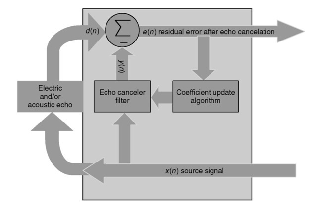
Figure 3.15 Principle behind an echo canceler.
One of the most common algorithms is the recursive least mean squares (LMS) algorithm, which computes the optimal h(k) using a descent algorithm. After each new sample x (n), the h(k) coefficients are updated as follows, where a is the descent algorithm step size parameter:

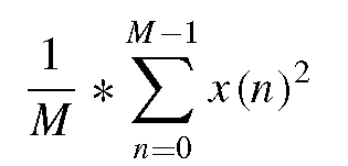
A larger step size accelerates convergence while slightly decreasing the quality of echo cancelation. The step size should be smaller than 1/(10*iV*Signal power) to ensure stability. Signal power can be approximated by:
3.3.4.3
Usage of echo cancelers
Electric (hybrid) echo cancelers (EECs) are also called line echo cancelers. They are inserted right after the hybrid, located between the 4-wire section of the network (the packetized network in the case of VoIP) and the 2-wire portion (Figure 3.16).
Acoustic echo cancelers are usually implemented in the phone itself.
Many national PSTN networks do not have line echo cancelers due to the relatively small transmission delays. Telephony networks that introduce longer delays can be connected to such PSTNs only though line echo cancelers. For example, in the GSM system, one-way delay is around 100 ms due to:
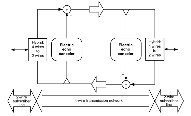
Figure 3.16 Insertion of echo cancelers in a network.
• A frame length of 20 ms.
• A processing delay of about 20 ms (depending on the handset s DSP).
• Interleaving for channel protection.
• Buffering and decoding.
So, an EEC must be included in the mobile switching center (MSC) as shown in Figure 3.17.
The situation is quite similar to that of a VoIP network, where line echo cancelation must be done in the VoIP gateways connected to the PSTN. If line echo cancelation is of insufficient quality, the user on the IP side will hear echo.
VoIP devices can also introduce acoustic echo. The worst examples are PCs with older VoIP software (without acoustic echo cancelation, or AEC). These PCs must be used with headsets in order to reduce echo as much as possible. Note that many headsets are not designed for this (e.g., many headsets have a microphone attached to one of the side speakers, allowing mechanical transmission of speaker vibrations to introduce echo). Some high-end active headsets, as well as dedicated soundboards, now include an AEC module, but the more recent PC VoIP software is now capable of performing the AEC algorithm, making it possible to use standard headsets or even have a hands-free conversation (Figure 3.18).
In a VoIP to PSTN call, if the AEC of the IP phone or the PC is insufficient, echo will be heard at the PSTN end.
The performance of an echo canceler involves many parameters (see G.168 for more details). The most important are echo return loss enhancement, or ERLE (in dB), the amount by which the echo level between the 5in and Sout port is reduced (see Figure 3.13),
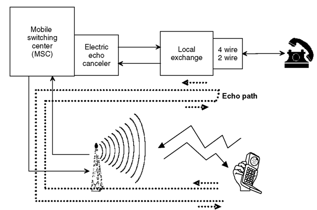
Figure 3.17 EEC required at the interface with the cellular network.
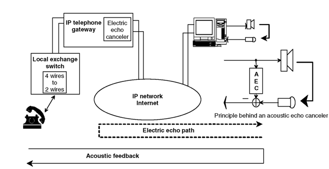
Figure 3.18 Softphones have to provide acoustic echo cancelation.
and the size of the window modeling the impulse response (some echo cancelers are optimized to cancel all echoes coming with a delay of 0 to Tmax, some echo cancelers are optimized to model only echoes coming with a delay of Tmin to Tmax). Other parameters include convergence time and quality of double-talk detection.
