3.4
3.4.1
Influence of the operating system
Most IP phone applications are just regular programs running on top of an operating system, such as Windows. They access sound peripherals through an API (e.g., the Wave API for Windows), and they access the network through the socket API.
As you speak the sound card samples the microphone signals and accumulates samples in a memory buffer (it may also perform some basic compression, such as G.711 encoding). When a buffer is full the sound card tells the operating system, using an interrupt, that it can retrieve the buffer, and stores the next samples in a new buffer, etc.
Interrupts stop the regular activities of the operating system and trigger a very small program called an interrupt handler which in our case may simply store a pointer to the sound buffer for the program that has opened the microphone.
The program itself, in the case of the Wave API, registered a callback function when it opened the microphone to receive the new sample buffers, and the operating system will simply call this function to pass the buffer to our IP phone application.
When the callback function is enacted, it will check that there are enough samples to form a full frame for a compression algorithm, such as G.723.1, and if so put the resulting compressed frame (wrapped with the appropriate RTP information) on the network using the socket API.
The fact that samples from the microphone are sent to the operating system in chunks using an interrupt introduces a small accumulation delay, because most operating systems cannot accommodate too many interrupts per second. For Windows many drivers try not to generate more than one interrupt every 60 ms. This means that on such systems the samples come in chunks of more than 60 ms, independent of the codec used by the program. For instance, a program using G.729 could generate six G.729 frames and a program using G.723.1 could generate two G.233.1 frames for each chunk, but in both cases the delay at this stage is 60 ms, due only to the operating system s maximum interrupt rate.
The self same situation occurs when playing back the samples, resulting in further delays because of socket implementation.
The primary conclusion of this subsection is that the operating system is a major parameter that must be taken into account when trying to reduce end-to-end delays for IP telephony applications. To overcome these limitations most IP telephony gateways and IP phone vendors use real-time operating systems, such as VxWorks (by Wind River Systems) or Nucleus, which are optimized to handle as many interrupts as needed to reduce this accumulation delay.
Another way of bypassing operating system limits is to carry out all the real-time functions (sample acquisition, compression, and RTP) using dedicated hardware and only carry out control functions using the non-real-time operating system. IP telephony board vendors, such as Natural Microsystems, Intel, or Audiocodes, use this type of approach to allow third parties to build low-latency gateways with Unix or Windows on top of their equipment.
3.4.2
The influence of the jitter buffer policy on delay
An IP packet needs some time to get from A to B through a packet network. This delay tAB = tarrival — tdeparture is composed of a fixed part L characteristic of average queuing and propagation delays and a variable part characterizing jitter as caused by the variable queue length in routers and other factors (Figure 3.19).
Terminals use jitter buffer to compensate for jitter effects. Jitter buffer will hold packets in memory until funbuffer — fdeparture = L + J. The time of departure of each packet is known by using the time stamp information provided by RTP. By increasing the value of J, the terminal is able to resynchronize more packets. Packets arriving too late (farrival > funbuffer) are dropped.
Terminals use heuristics to tune J to the best value: if J is too small too many packets will be dropped, if J is too large the additional delay will be unacceptable to the user. These heuristics may take some time to converge because the terminal needs to evaluate jitter in the network (e.g., the terminal can choose to start initially with a very small buffer and progressively increase it until the average percentage of packets arriving too late drops below 1%). For some terminals, configuration of the size of jitter buffer is static, which is not optimal when network conditions are not stable.
Usually endpoints with dynamic jitter buffers use the silence periods of received speech to dynamically adapt the buffer size: silence periods are extended during playback, giving more time to accumulate more packets and increase jitter buffer size, and vice-versa. Most endpoints now perform dynamic jitter buffer adaptation, by increments of 5-10 ms.
A related issue is clock skew, or clock drift. The clocks of the sender and the receiver may drift over time, causing an effect very similar to jitter in the network. Therefore, IP phones and gateways should occasionally compensate for clock drift in the same way they compensate for network jitter.
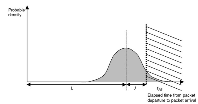
Figure 3.19 Influence of jitter buffer size on packet loss.
3.4.3
The influence of the codec, frame grouping, and redundancy
3.4.3.1
Frame size, number of frames per packet
Most voice coders are frame-oriented; this means that they compress fixed size chunks of linear samples, rather than sample per sample (Figure 3.20). Therefore, the audio data stream needs to be accumulated until it reaches chunk size, before being processed by the coder. This sample accumulation takes time and therefore adds to end-to-end delay. In addition, some coders need to know more samples than those already contained in the frame they will be coding (this is called look-ahead).
Therefore, in principle, the codec chosen should have a short frame length in order to reduce delays on the network.
However, many other factors should be taken in consideration. Primarily, coders with larger frame sizes tend to be more efficient, and have better compression rates (the more you know about something the easier it is to model it efficiently). Another factor is that each frame is not transmitted ‘as is through the network: a lot of overhead is added by the transport protocols themselves for each packet transmitted through the network. If each compressed voice frame is transmitted in a packet of its own, then this overhead is added for each frame, and for some coders the overhead will be comparable if not greater than the useful data! In order to lower the overhead to an acceptable level, most implementations choose to transmit multiple frames in each packet; this is called ‘bundling (Figures 3.21).
If all the frames accumulated in the packet belong to the same audio stream, this will add more accumulation delay. In fact, using a coder with a frame size of f and three frames per packet is absolutely equivalent, in terms of overhead and accumulation
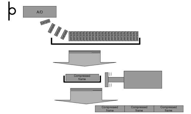
Figure 3.20 Concept of audio codec ‘frames’.
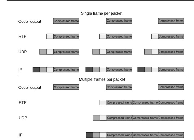
Figure 3.21 Influence of bundling on overhead.
delay, to using a coder with a frame size of 3/ and one frame par packet. Since a coder with a larger frame size is usually more efficient, the latter solution is likely to be more efficient also.
Note that if the operating system gives access to the audio stream in chunks of size C ms rather than sample per sample (see Section 3.4.1), then samples have already been accumulated and using a coder with a larger frame size / introduces no additional overhead as long as /< C.
A much more intelligent way of stacking multiple frames per packet in order to reduce overhead without any impact on delay is to concatenate frames from different audio streams, but with the same network destination, in each packet. This situation occurs frequently between corporate sites or between gateways inside a VoIP network. Unfortunately, the way to do this RTP-multiplexing (or RTP-mux) has not yet been standardized in H.323, SIP, or other VoIP protocols. The recommended practice is to use TCRTP (tunneling-multiplexed compressed RTP), an IETF work-in-progress which combines L2TP (Layer 2 Tunneling Protocol, RFC 2661), multiplexed PPP (RFC 3153), and
compressed RTP (RFC 2508, see ch. 4 p. 176). 3.4.3.2 Redundancy, interleaving
Another parameter that needs to be taken into account when assessing the end-to-end delay of an implementation is the redundancy policy. A real network introduces packet
loss, and a terminal may use redundancy to be able to reconstruct lost frames. This can be as simple as copying a frame twice in consecutive packets (this method can be generalized by generating, after each group of N packets, a packet containing the XORed value of the previous N packets, in which case it is called FEC, for forward error correction) or more complex (e.g., interleaving can be used to reduce sensitivity to burst packet loss).
Note that redundancy should be used with care: if packet loss is due to congestion (the most frequent case), redundancy is likely to increase the volume of traffic and as a consequence increase congestion and network packet loss rate. On the other hand, if packet loss was due to an insufficient switching capacity (this is decreasingly likely in recent networks, but may still occur with some firewalls), adding redundancy by stacking multiple redundant frames in each packet will not increase the number of packets per second and will improve the situation.
Redundancy influences end-to-end delay because the receiver needs to adjust its jitter buffer in order to receive all redundant frames before it transfers the frame to the decoder (Figure 3.22). Otherwise, if the first frame got lost, jitter buffer would be unable to wait until it has received the redundant copies, and they would be useless! This can contribute significantly to end-to-end delay, especially if the redundant frames are stored in noncontiguous packets (interleaving) in order to resist correlated packet loss. For this reason this type of redundancy is generally not used for voice, but rather for fax transmissions which are less sensitive to delays.
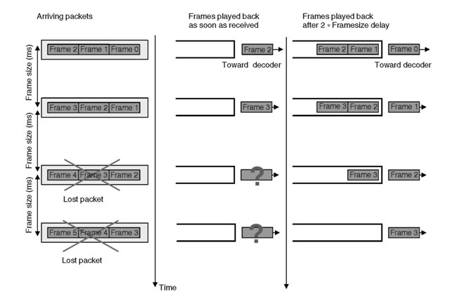
Figure 3.22 FEC or interleaving type of redundancy only works when there is an additional delay at the receiver buffer.
3.4.4
Measuring end-to-end delay
In order to assess the delay performance of IP telephony hardware or software, it is necessary to simulate various network conditions, characterized by such parameters as average transit delay, jitter, and packet loss. Because of the many heuristics used by IP telephony devices to adapt to the network, it is necessary to perform the end-to-end delay measurement after allowing a short convergence time. A simple measurement can be done according to the following method:
(1) IP telephony devices’ IP network interfaces are connected back to back through a network simulator.
(2) The network simulator is set to the proper settings for the reference network condition considered for the measurement; this includes setting the average end-to-end delay L, the amount of jitter and the jitter statistical profile, the amount of packet loss and the loss profile, and possibly other factors, such as packet desequencing. Good network simulators are available on Linux and FreeBSD (e.g., NS2: www.isi.edu).
(3) A speech file is fed to the first VoIP device with active talk during the first 15 s (Talk1), then these follows a silence period of 5 s, then active talk again for 30 s (Talk2), then a silence period of 10 s.
(4) The speech file is recorded at the output of the second VoIP device.
(5) Only the Talk2 part of the initial file and the recorded file is kept. This gives the endpoint some time to adapt during the silence period if a dynamic jitter buffer algorithm is used.
(6) The average level of both files is equalized.
(7) If the amplitude of the input signal is IN(f), and the amplitude of the recorded signal is OUT(f), the value of D maximizing the correlation of IN(f) and OUT(f + D)is the delay introduced by the VoIP network and the tested devices under measurement conditions. The correlation can be done manually with an oscilloscope and a delay line, adjusting the delay until input and output speech samples coincide (similar envelopes and correlation of energy), or with some basic computing on the recorded files (for ISDN gateways the files can be input and recorded directly in G.711 format).
The delay introduced by the sending and receiving devices is D — L,sinceL is the delay that was introduced by the network simulator. With this method it is impossible to know the respective contributions to the delay from the sending and the receiving VoIP devices.
Note that a very crude, but efficient way of quickly evaluating end-to-end delay is to use the Windows sound recorder and clap your hands (Figure 3.23). The typical mouth-to-ear delay for an IP phone over a direct LAN connection is between 45 ms and 90 ms, while VoIP softphones are in the 120 ms (Windows XP Messenger) to 400 ms range (NetMeeting and most low-end VoIP software without optimized drivers).
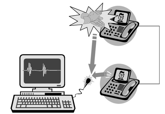
Figure 3.23 Poor man’s delay evaluation lab.
