3.5
3.5.1
The G.131 curve
The degree of annoyance of talker echo depends on the amount of delay between the original signal and the echo, and on the attenuation of the echo signal compared with the original. This attenuation is characterized by the ‘talker echo loudness rating (TELR) as described in G.122 and annex A/G.111. A higher value of TELR represents better echo cancelation. Note that, because of quantization noise on the original signal, it is impossible to achieve a perfect echo cancelation (typically about 55 dB at best).
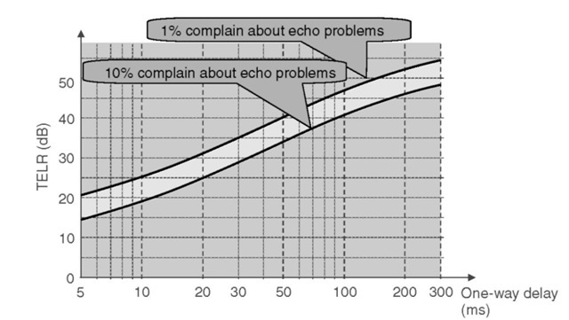
G.131 provides the minimum requirements on TELR as a function of the mean oneway transmission time T. According to G.131 (Figure 3.24), conditions are generally acceptable when less than 1% of the users complain about an echo problem. The second curve, where 10% of users complain, is an extreme limit that should be allowed only exceptionally.
Figure 3.24 clearly shows that echo becomes more audible as delay increases. This is the reason echo is such a problem in all telephony technologies that introduce high delays. This is the case for most packet voice technologies, for networks that use interleaving for error protection (e.g., cellular phones), and for satellite transmissions in general.

Figure 3.24 G.131 one-way delay versus echo perception.
3.5.2
Evaluation of echo attenuation (TELR)
3.5.2.1
Overview of signal level measurement (dB, dBr, dBm0, etc.)
A discussion of units can be found in G.100 annex A. Here is a short summary:
• Relative power is measured in dB. A signal of P1 mW is at level L dB compared with a signal of P2 mW if L = 10log10(P1/P2). For relative voltages, currents, or acoustic pressure, the formula uses a multiplicative factor of 20 instead of 10 (power depends on the square of voltage/current or pressure).
• dBm refers to a power measurement in dB relative to 1 mW.
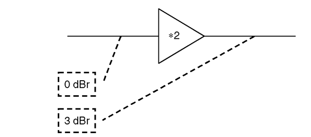
• dBr is used to measure the level of a reference 1,020-Hz signal at a point the compared with the level of that same reference signal at the reference point (the 0-dBr point). For instance, if the entrance of an *2 amplifier (Figure 3.25) is the 0-dBr point, the output is a +3-dBr point. Digital parts of the network are by convention at 0 dBr (unless digital gain or loss is introduced). To determine the dBr level at the analog end of a

Figure 3.25 dBr levels at the input and output of a *2 amplifier.
coder or decoder, G.101 defines a digital reference sequence (DRS). When decoding the DRS, if the output of the decoder is at R dBm, then it is an R-dBr point.
• dBmO is used to measure the absolute level in dBm which a signal would have when passing through the reference point (0-dBr point). For instance, if the power of a signal at the output of the Figure 3.25 amplifier is 10 dBm, then it is a 7-dBm0 signal.
3.5.2.2
TELR for analog and digital termination lines
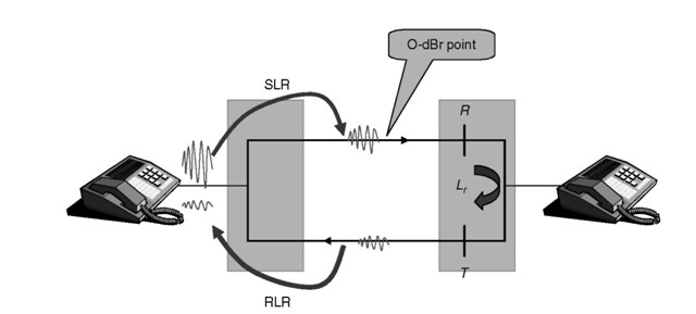
Recommendation G.131 uses the reference circuit of Figure 3.26 to evaluate talker echo attenuation. The send loudness rating (SLR) and receive loudness rating (RLR) model the acoustic-to-electric efficiency of the emitter and the receiver, respectively (see ITU recommendation P.79). For typical phone sets G.121 states that SLRtarget = 7dB, SLRmin = 2 dB, RLRtarget = 3 dB, RLRmin = 1 dB. For digital phones, the recommended
values are SLR = 8dBandRLR= 2dB.
For an analog phone at the distant side TELR = SLR + RLR + R + T + Lr ,where R and T stand for additional loss introduced in the analog circuit in order to have a 0-dBr point at the exchange. Most analog phone connections have an Lr > 17 dB for an average length of subscriber cable; however, in some networks it can be 14 dB with a standard deviation of 3 dB. In many networks R + T = 6dB.
For a digital phone at the distant side TELR = SLR + RLR + TCL, where TCL is terminal coupling loss. IP phones are digital phones. For software phones the values of SLR and RLR can be affected by sound card settings (microphone volume, speaker volume), and properly implemented software should apply digital attenuation to make sure that the resulting SLR and RLR provide the recommended values for the voice level in the VoIP network. Most digital handsets have a TCL of 40-46 dB, although lower end phones may have a TCL as low as 35-40 dB.

Figure 3.26 Parameters influencing TELR.
When the intrinsic TELR value of the network is too low for the expected network delay, an echo canceler must be added (in the handset for acoustic echo, in the network for line echo) in order to increase the resulting TELR to a value that is acceptable.
3.5.2.2.1
Examples
For SLR = 7 dB, RLR = 3dB, Lr = 14 dB, R + T = 6 we get a TELR of 30 which leads to an acceptable limit for the one-way delay of 18 ms (33 ms in the limiting case). For a ‘loud’ telephone set with SLR = 2 dB, RLR = 1dB, and an Lr of 8 dB we get a TELR of 17 and the limiting case is now 7 ms!
When ringing a digital handset (TCL = 45 dB) with the talker’s phone at SLR = 7dB, RLR = 3 dB we get a TELR of 55 dB and the one-way delay is ‘acceptable’ up to 400 ms regarding echo perception (but such a one-way delay is already impacting the interactivity of the conversation).
3.5.2.3
VoIP circuits
The IP telephony circuit is subject to the same echo/delay constraints as any other telephony technology. With current IP technology, delays of 200-300 ms for one-way transmission are still common over wide area networks. Other delay factors (encoding delay, jitter buffers, etc.) may add as much as 100 ms. Therefore, all VoIP networks require state-of-the-art echo cancelation, with a TELR value of at least 55 dB. Note that this is close to the highest achievable value for G.711 encoded voice signals, due to the quantization noise that is introduced by G.711. With most echo cancelers, this echo cancelation level can be reduced to about 30 dB under double-talk conditions.
3.5.2.3.1
IP software phone to IP phone or IP software phone
In this case if we assume SLR + RLR = 10 dB, then the echo loss of the distant IP phone must be at least TCL = 45 dB. On a software phone, this might be implemented in the audio peripherals (soundboard, headset) or by the IP telephony software itself.
3.5.2.3.2
IP phone to a regular phone
3.5.2.3.2.1 IP phone to digital or cellular phone At the ISDN phone end, only acoustic echo is generated since there is no hybrid. Most ISDN phones have a TCL value of 45 dB, so the IP telephony gateway does not need to perform echo cancelation at the ISDN phone end if the connection is digital end to end (this is rarely the case, except in Germany).
Obviously, the IP phone needs to have an echo canceler as well, otherwise the digital phone user will hear echo.
In the early days of VoIP, many gateway demonstrations made phone calls to ISDN or cellular phones. In the case of cellular phones, some vendors even explained that this was the worst case scenario because, after all, you were calling a cellular phone. In fact, this was done on purpose to hide the lack of an echo-canceling algorithm in the IP telephony gateway! The cellular phone itself is a 4-wire device (no electric echo) and includes a
powerful acoustic echo canceler. The cellular phone network interface with the regular phone network is also made via echo cancelers.
3.5.2.3.2.2 IP phone to PSTN user In this case the PSTN phone will generate hybrid echo and acoustic echo. Since propagation time in the PSTN is usually low, many national links may not implement sufficient echo cancelation (if implemented at all). Therefore, the gateway must implement echo cancelation. In some cases there will already be an echo canceler in the PSTN path, which may cause some signal degradation (e.g., voice clipping), but even such degradation is preferable to the risk of not having any echo cancelation.
Canceling electric and acoustic echo is difficult because their characteristics in terms of attenuation and, more importantly, delay are very different. Acoustic echo signal components are typically spread over about 50 ms (office environment), while electric echo signals are typically spread over 13 ms. Echo cancelers are often characterized by the maximum skew between the signals that compose the echo. This signal is a superposition of signals st that are a copy of the original signal but attenuated by a factor At and delayed by a factor of D + dt. D is introduced by the voice transport network between the echo canceler and the source of echo. If a gateway is implemented in a country the size of France, for instance, D is below 64 ms in 90% of the cases, including call rerouting.
Some echo cancelers optimized for use in corporate equipment only work with D = 0 and 0 <d{ < Max skew (e.g., 18 ms). Some network echo cancelers can work with D as large as 500 ms and 0 <dt < Max skew. Only variation of the delay (maximum skew) requires memory in the echo canceler. Since most echo cancelers are implemented as FIR filters on signals that were originally G.711 signals, the memory (therefore, variation of the delay) supported by the echo canceler is sometimes mentioned as ‘taps’ (i.e., a memory cell for one sample, or 0.125 ms). An acoustic echo canceler requires more than 400 ‘taps’ (50 ms), while a line echo canceler requires about 100 ‘taps’ (12.5 ms). Most VoIP gateways have an echo canceler with a memory of at least 32 ms, (many go up to 64 or even 128 ms), and most of them only cancel hybrid echo, which explains why some echo can still be heard sometimes when talking to people with low-quality loudspeaker phones.
Note that it should be possible to disable this echo canceler, either statically (if the gateway is connected to a network already performing echo cancelation) or dynamically (if a modem connection is detected, because modems perform their own echo cancelation as required by recommendation G.168).
3.5.3
Interactivity
In the previous examples the term ‘acceptable only considered echo. Interactivity is another factor that must also be considered. Usually, a delay below 150 ms one-way provides good interactivity. A one-way delay between 150 ms and 300 ms provides acceptable interactivity (satellite hop). A one-way delay in excess of 400 ms should be exceptional (in the case of two satellite hops it is about 540 ms) and is the limit after
Table 3.1 ITU interactivity classes
| Class | One-way delay (ms) | |
| 1 | 0-150 | Acceptable for most conversations. Only the most interactive tasks will perceive a substantial degradation |
| 2 | 150-300 | Acceptable for communications with low interactivity (communication over satellite link) |
| 3 | 300-700 | Conversation becomes practically half-duplex |
| 4 | Over 700 | Conversation impossible without some training to half-duplex communications (military communication) |
Table 3.2 Communication impairment caused by one-way delay
| One-way | Index of communication |
| delay (ms) | impairment (%) |
| 200 | 28 |
| 450 | 35 |
| 700 | 46 |
which the conversation can be considered half-duplex. ITU recommendation G.114 lists classes of interactivity and quality as a function of delay (Tables 3.1 and 3.2).
When there are large delays on the line, the talker tends to think that the listener has not heard or paid attention. He will repeat what he said and be interrupted by the delayed response of the called party. Both will stop talking… and restart simultaneously! With some training it is quite possible to communicate correctly, but the conversation is not natural.
3.5.4
Other requirements
3.5.4.1
Average level, clipping
Gateways and transcoding functions to the PSTN should implement automatic-level control to respect ITU recommendation G.223: ‘The long term average level of an active circuit is expected to be — 15 dBm0 including silences. The average level during active speaking periods is expected to be —11 dBm0.’ The methodology for measuring active speech levels can be found in ITU recommendation P.56.
Note that PCM coding is capable of handling a maximum level of +3.14 dBm0 in the A law (+3.17 dBm0 in the i law). The gateways should absolutely avoid clipping, since this would adversely disturb the echo cancelers in the network (introduction of nonlinearities). As the average-to-peak power ratio of voice signals is about 18 dB, this imposes an average level not exceeding —15 dB.
Even IP phones and software phones should respect the average levels expected on a transmission line. Since microphone sensitivity can be adjusted on most operating systems, software phones should adjust accordingly to avoid sending too high or too low signals over the VoIP network.
3.5.4.2
Voice activity detection
VAD algorithms are responsible for switching the coder from ‘active speech mode’ to ‘background noise transmission mode’ (this can also be ‘transmit nothing mode’). If they are not implemented properly these algorithms may clip parts of active speech periods: beginning of sentences, first syllables of words, etc.
A general guideline for a good VAD algorithm is to keep the duration of clipped segments below 64 ms and have no more than 0.2% of the active speech clipped. These guidelines are part of ITU recommendation G.116. More detailed information is available in ‘Subjective effects of variable delay and speech loss in dynamically managed systems’, J. Gruber and L. Strawczynski, IEEE GLOBECOM ’82, 2, pp. 7.3.1-7.3.5.
3.5.5
Example of a speech quality prediction tool: the E-model
The E-model was originally developed in ETSI for the needs of network planning and later adopted by the ITU as recommendation G.107. It allows the subjective quality of a conversation as perceived by the user to be evaluated. The E-model appraises each degradation factor on perceived voice quality by a value called an ‘impairment factor’. Impairment factors are then processed by the E-model which outputs a rating R between 0 and 100. The R value can be mapped to a mean opinion score, conversational quality evaluation (MOScqe) value between 1 and 5, or to percent good or better (%GoB), or to percent poor or worse (%PoW) values using tables. An R value of 50 is very bad, while an R value of 90 is very good.
The E-model takes into account parameters that are not considered in the G.131 curve (Figure 3.24), such as the quality of the voice coder (degradation factor Ie) and frame loss (degradation factor BP1). Most voice coders have been rated for their impairment factor without frame loss, and consequently the E-model (available as commercial software from various vendors) can readily be used to evaluate perceived voice quality through an IP telephony network with no packet loss and low jitter. This work was published by the T1A1.7 committee in January 1999.
Impairment factor parameters are evaluated from real subjective tests to calibrate the model (e.g., see G.113). Therefore, the usability of the E-model for a particular technology depends on how much calibration has been done previously on this technology. The E-model is only useful if it is used correctly. An impairment factor for a coder measured under specific loss profiles is not valid for other loss profiles (e.g., if there is correlated loss). IP telephony introduces many new types of perturbations that do not exist on traditional networks, such as the delay variation that may be introduced by endpoints trying to dynamically adjust the size of jitter buffers, voice clipping introduced by VAD algorithms, or correlated loss introduced by frame grouping. Some R&D labs that specialize
in voice quality and network planning have released new versions of the E-model with specific support for IP telephony degradations. This should lead to an update of the ITU specification in 2005 (currently known as P.VTQ).
One of the interesting aspects of the E-model is that it also takes into account psychological parameters that do not the influence absolute voice quality, but the perception of the user. For instance, the ‘expectation’ impairment factor takes into account the fact that most users expect to have degraded voice quality when using a cellular phone, and therefore will be more indulgent … and complain less, for the same level of quality, than if they had been using a normal phone and vice versa: if a cellular phone achieves similar voice quality to a normal fixed phone, many users will actually find it better than the normal phone. IP phone manufacturers may have to find a recognizable design if they want to benefit from the ‘VoIP expectation factor’!
