Spacelab is the European contribution to the Post Apollo Program. U.S. President Nixon made an offer in 1969 to the eight member states of the European Space Agency to participate in the planned recoverable launcher area in developing the Space Shuttle and its payloads.
Spacelab is a reusable, multipurpose, modular laboratory and in the first 10 years of Space Shuttle operation, became its major payload. This payload remained attached to the Orbiter during the whole flight and maintained certain dependences. Spacelab was not a habitat, so that the Mission and Payload Specialists stayed in the Orbiter during take-off and landing and used it also as living quarters.
Spacelab was designed for a 10-year lifetime and/or 50 missions. Inside the laboratory, called the module, a shirtsleeve atmosphere for the astronauts was required; experiments on the outside had to be conducted in the open space on a pallet. Both module and pallet were accommodated inside the Shuttle payload bay and remained attached to the Shuttle during the mission (Fig. 1). This fact limited the time of a Spacelab mission to the time of a Shuttle flight.
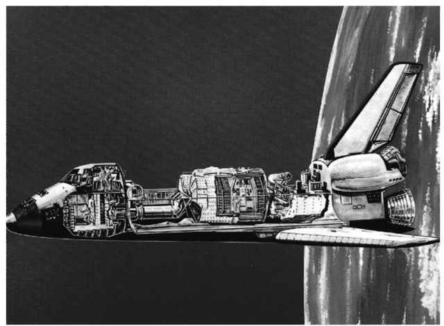
Figure 1. Spacelab.
On 4 June 1974, the contract to design and build Spacelab was given by the European Space Agency (ESA) to an industrial consortium of companies from eight European countries under the leadership of the German space company ERNO Raumfahrttechnik in Bremen. The contract, won in a competition, was based on a modular design of the laboratory (Fig. 2) that applied state-of-the-art technology and experience in aircraft design to solutions of the turnaround requirements of frequent reuses.
For most of the time from 1974 to 1983, the Spacelab development ran parallel to the Shuttle development on a no exchange of funds basis to use common hardware and subsystems as much as possible.
The Modular Concept
The multipurpose objective of Spacelab led to a modular design to meet the needs of missions of very different natures for the module as well as for the pallet. To keep the cost down, the module and pallet elements were made a standard size, each 2.70 m. This allowed using standardized handling and transportation equipment and several combinations of module and pallet elements for the different missions. For pallet only modes, a special Igloo was developed to house the equipment that controlled the functions of the pallet and its payloads.
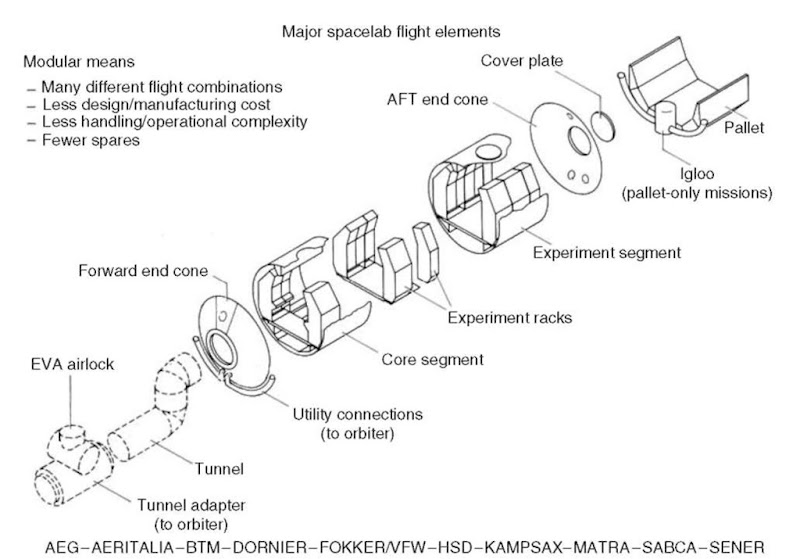
Figure 2. The modular concept Major Spacelab Flight elements.
The Design Concept
The general shape and dimensions for this Shuttle payload were determined by the Shuttle payload bay. The Spacelab module has a cylindrical shape that is the diameter of the Shuttle payload bay. Although not needed in space, the cylinder contained a floor on which racks are mounted along the sidewalls.
The required 50 reuses and therefore, the corresponding 50 refurbishments on Earth demanded a floor/ceiling configuration to allow proper handling when under gravitational forces. This fact led to the solution to mount the racks on floor elements which could be rolled out of the cylinder like freight containers out of an airplane (Fig. 3). By this concept, the payload and experiments could be removed from the laboratory on their floor elements and shipped directly to their origin, and the new payload could be rolled in without any delay. By using this solution, the originally required 2-week turnaround time on the ground between missions could be achieved.
An aircraft structure design was selected for the pallet that allowed plain standardized surfaces for payload mounting and easy handling. A special instrument pointing system (IPS) was designed and built to be mounted on the pallet to allow high accuracy pointing for payloads, thus eliminating errors from the Shuttle attitude control system.
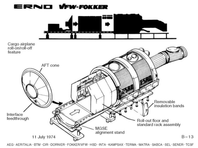
Figure 3. Payload integration—system level.
An airlock on top of the module provided access of experiments to open space for direct exposure, and a window provided a view to the outside. Mission Specialists and Payload Specialists entered the laboratory through a tunnel from the lower aft flight deck of the Orbiter into Spacelab (Fig. 4). The 1.1-m diameter tunnel was not part of the European delivery program.
The Module Structure
The basic structural element of the Spacelab module was a cylindrical segment 2.70 m long and 4.06 m in diameter. This cylindrical shell was made of AL- 2219 alloy sheets that had a chemically milled inside waffle pattern and were welded at the seams. End flanges of forged aluminum alloy stabilized the cylinder and were used to join the segments to each other and to the end cones. Two of these segments, two end cones, internal floors, and several racks were part of the initial module structure’s flight hardware deliveries. Cutouts in the shell for the window and the airlock required local strengthening to avoid distortion problems and to ensure pressure-tight mating surfaces (Fig. 5).
The floor could take loads up to 300 kg/m at the center and up to 500 kg/m at the outsides, and the racks could hold a load of 580 kg/m per side. The module and the pallet were supported in the Shuttle payload bay by trunnions and keel fittings which had to carry the weight of the loaded module on the ground and all loads imposed during launch and landing. A special surface finish had to be developed for these attachments to meet the very low friction coefficient to allow for twisting and bending of the Shuttle payload bay imposed by changing pressure, thermal loads, and landing impact. The module segment was attached by three fittings to the Orbiter payload bay, two trunnions and one keel fitting.
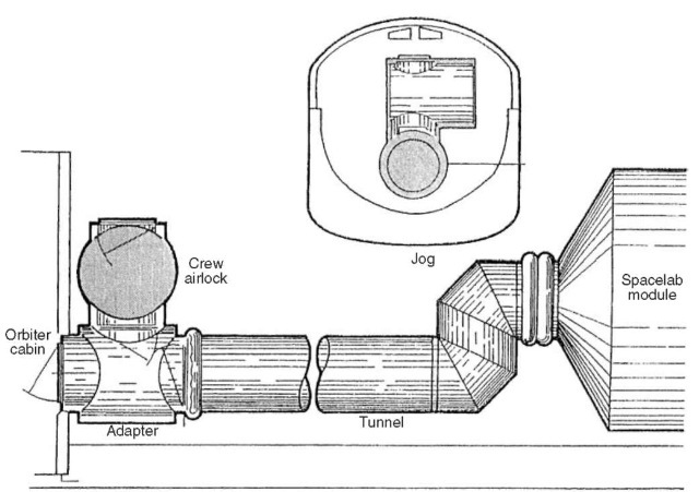
Figure 4. Offset concept for the transfer tunnel showing the jog required to permit centerline entrance to the Spacelab module.
The subsystem equipment which was needed to run the laboratory was to be placed in two double racks at the forward end of the module and on a subfloor beneath the main floor. All other single or double racks were available for the payload. There were up to seven overhead storage containers in each segment attached to overhead supports mounted on the module ceiling, which also served as attachments for the racks.
The Pallet Structure
Like the module segments, the pallet segments were identical modular units 2.90 m long that could be mounted separately or together in pallet trains of two or three units or in combination with one or two module segments in the Shuttle payload bay. The basic U-shaped design allowed mounting experiments of up to 3000 kg on the inside or about 1100 kg/m equally distributed on standardized panels and on hard points that had an available volume of 33 m3 per pallet. Very thin aluminum faceplates were used on the panels to save weight. Four symmetrical support fittings were applied to suspend the pallet in the Orbiter pay-load bay (Fig. 6).
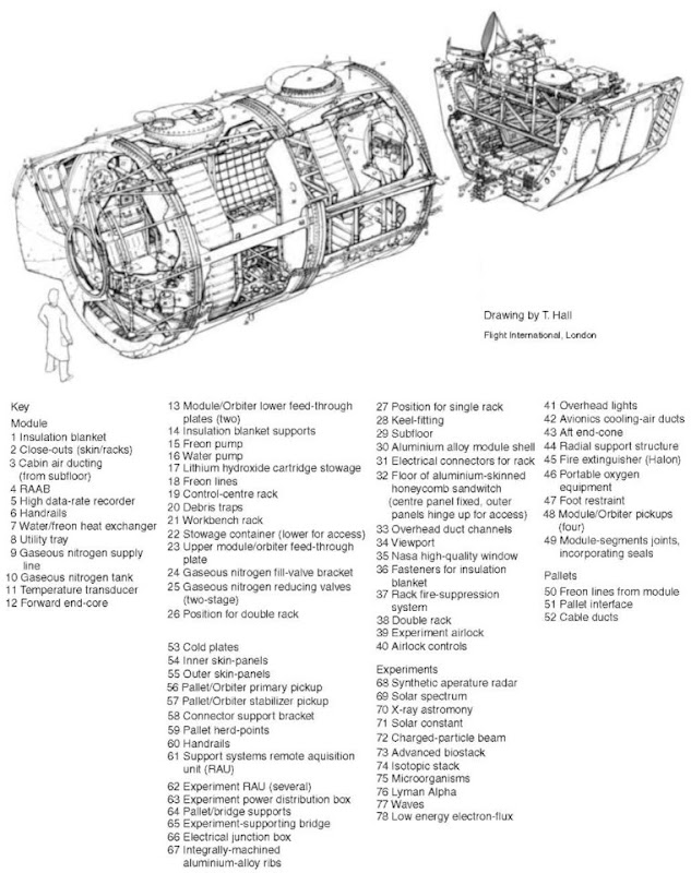
Figure 5. Spacelab, Europe’s space laboratory.
For the pallet-only missions, a special equipment container, the so-called Igloo, was developed. The primary structure of the Igloo was a cylinder-shaped locally stiffened shell made of aluminum alloy forged rings. The lower end was closed, and the upper end was a mounting flange. The Igloo was attached directly to the forward end frame of the foremost pallet. The secondary internal structure was mounted on the primary structure and was finally closed by a cylindrical cover which was also a shell of aluminum alloy closed at the top and mated to the top flange of the primary structure. For the connection to the Orbiter, feed-through of utility lines was provided by penetrations of the Igloo. The thermal control of the Igloo was both active and passive; most equipment was cold-plated to the FreonTM system. The internal atmosphere was air, and a drying agent was included to avoid condensation after closing the cover. Nitrogen was added via a fill valve to ensure sufficient internal pressure during the mission. Overpressure safety protection was provided redundantly by a relief valve and a burst disk.
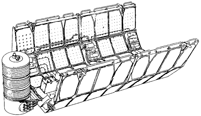
Figure 6. Pallet structure.
The Instrument Pointing System
One of the most interesting and ambitious subsystems was the instrument pointing system (IPS) for telescopes and sensors. The IPS provided three-axis attitude control and stabilization of payloads up to 2000 kg mounted on the pallet and exposed directly to open space. The pointing accuracy was 71 arcsecond for a payload that has a diameter up to two meters and a length up to 4 meters (Fig. 7). The design solution was an end-mounted approach in which the three gimbal systems would be mounted on the pallet providing support to a circular mounting frame to which the optical instrument would be attached. In zero gravity operation, the gimbal support structure would handle only the momentum of the instrument masses. During launch and landing, a payload gimbal separation mechanism would separate the IPS and the payload, a gimbal latch mechanism would lock the gimbal system, and a payload clamp assembly would provide a three-point clamping of the payload.
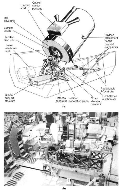
Figure 7. (a) Instrument pointing subsystem (b) Spacelab experiments testing.
The Environmental Control Subsystem
The environmental control subsystem (ECS) of Spacelab had to ensure the requirements of sea-level pressure and a shirtsleeve atmosphere for the crew and the experiments in the laboratory. It was agreed among the partners that the Orbiter would supply the oxygen and the Spacelab would provide its own nitrogen as well as the components to regulate and distribute the air supply throughout the module and remove excess moisture and carbon dioxide. A high-pressure nitrogen tank was mounted on the outside of the module. The CO2 created by the breathing of the crew was absorbed by LiOH cartridges mounted on the subfloor underneath the main floor of the Spacelab cabin as well as by the two air fans and the contamination filters.
The heat generated by the module and the pallets was transferred to the Orbiter thermal control system. The minimum cabin temperature was supposed to be 19.5°C within a range of 18-27°C and the humidity between 30 and 70%. One circuit of air served the interior of the module cabin at a flow rate of 5-12 m/ min, and a second circuit served the cooling of the equipment mounted in the racks. By passing through a heat exchanger, the heat load of the air was transferred to a flow of water that was pumped through an Orbiter payload heat exchanger to transfer the total Spacelab heat load finally to the externally mounted Orbiter radiators. The total capacity of this system was 5.8 kW.
A further component of the thermal control system was a FreonTM cooling circuit serving experiments mounted to cold plates on the pallet floor or lower sides. A total of eight such cold plates could be mounted on the pallet to accommodate experiments. Four thermal capacitors allowed storing of peak heat loads. As coolant, FreonTM 114 was used because water would freeze immediately when exposed to the outside environment of the pallets.
The Command and Data Management Subsystem
The most complicated subsystem of Spacelab is the command and data management subsystem (CDMS). It is an extension of the Orbiter telecommunication system which finally transmits data generated by the laboratory and its experiments which have been acquired by the CDMS and multiplexed in low-rate housekeeping and high-rate scientific data streams. NASA used two real-time data transfer systems. The Space Tracking and Data Network (STDN) transferred relatively low data rates of up to 192,000 bits/s from the Orbiter to the ground (downlink) and 72,000 bits/s from the ground to the Orbiter (uplink). Higher data rates were transmitted with the help of the Tracking and Data Relay Satellite System (TDRSS). This link allowed downlink data rates up to 50 million bits/s. On the ground, the data were received by ground stations in White Sands, New Mexico, via S-band or Ku-band through the geostationary satellites of the TDRSS. From there, they were relayed to the Payload Operations Control Center at the NASA center in Clearlake near Houston and to the Spacelab Data Processing Facility at the Goddard Space Flight Center in Greenbelt, Maryland.
The CDMS had to provide mass memory storage for the central computers and for the periods of time when the Shuttle was out of sight of the TDRSS storage of high-rate digital data. A high-rate multiplexer ensured the handling of up to 16 channels of 16-megabit-per-second data.
Onboard computers, remote acquisition units that interfaced the functional laboratory equipment and the experimental equipment to the data bus, voice digitizer and intercom equipment, data display/keyboards, input/output and interconnecting stations, and a high-rate digital recorder were further elements of the CDMS.
In principle, the CDMS was divided into two elements: the data processing assembly and the high-rate data assembly. In the data processing assembly, two remote acquisition units separately served the Spacelab subsystems and the experiments. Each of these parts had a computer, an input/ouput unit, and a 1-megabit-per-second digital data bus which was routed through the laboratory. Three keyboards and displays and the mass memory served the two parts. This assembly was to acquire data; to distribute timing and commands via the data bus; and to interface with the Orbiter multiplexer/demultiplexer, the pulse code modulation unit, and the master timing unit. The high-rate data assembly consisted of the high-rate multiplexer, the high-rate recorder, and the demultiplexer and high-rate data recorders on the ground. This assembly acquired data directly from experiments and time division multiplexed these data into a composite data stream of up to 48 megabits per second, which could be transmitted to the ground by the Ku-band communication system. Besides the high-rate data, some low-speed data, as well as digitized voice and timing data, could be added into this composite data stream.
The Electrical Power Distribution Subsystem (EPDS)
Spacelab received its power from the Shuttle Orbiter. The power was produced by three fuel cells that converted oxygen and hydrogen into electrical power by a chemical reaction. In orbit, the power of one of these three fuel cells could be dedicated to Spacelab. This meant providing 7 kW of dc at 28 volts. The maximum power for Spacelab could be raised to 12 kW for 15 minutes once within a 3-hour time frame. Inverters (400 Hz) in the laboratory could convert parts of the energy into three-phase ac power at 115 and 200 volts. Built-in control and regulation circuits provided protection for inverters and consumers against overvoltage and over current. During takeoff and landing, the available power for Spacelab was reduced to 1 kW because most of the experiments and subsystems were dormant in these mission phases. The total available quantity of oxygen and hydrogen in the Shuttle Orbiter was the factor limiting the total energy available for a mission. This limited a normal mission to about 300 kWh available for experiments in the Spacelab module configuration and 550 kWh in a Spacelab pallet-only configuration. Additional fuel cells in the Shuttle Orbiters “Columbia” and “Endeavour” allowed extending the mission’s duration to 2 weeks as far as the power was concerned.
Basically, of the 7 kW power available for Spacelab, 5 kW was required by the laboratory subsystems and mission-dependent equipment, leaving only 2 kW for the experiments; 2 kW in the case of the pallet-only mode, only 5 kW remained for experiments. The main power conditioning, distribution, and control of the power through a feeder from the Orbiter took place in a power control box. This box included a shunt regulator to limit the main bus voltage to 32 volts and melting fuses to prevent short circuits on the feeders. A subsystem power distribution box distributed the dc and ac power into dedicated subsystem feeders.
The Follow-On Production (FOP)
The NASA/ESRO MOU of 1973 provided for NASA, to procure at least one further Spacelab no later than 2 years before the delivery of the first, provided that it met the agreed specifications and schedules and was reasonable in price. This agreement was realized by a procurement contract signed at the end of January 1980 and a preceding letter contract for the procurement of the essential long-lead items.
The Mechanical Ground Support Equipment (MGSE)
Parallel to the development of the Spacelab module and pallet and their auxiliary subsystems, sophisticated ground support equipment had to be developed that mirrored the dimensions and accuracy requirements of the flight hardware. Besides the integration process in its different phases, ground handling included transport on the ground and in the air.
The modular design of Spacelab required a mechanical ground support equipment that allowed mating two modules and their two end cones on the ground to simulate the real flight configuration with respect to the accurate integration and verification of the O-ring seals. It also required mating a three-pallet train.
In addition to the integration equipment, the modules needed special transport equipment in which each module could be placed like a flat can, because its dimensions did not allow transport on the road in a normal upside position. Also, the eight double racks and four single racks, which were to hold avionics equipment and the experiments, had to be supported for integration, handling, and transport, including their floor sections onto which they were mounted.
Besides the mechanical support, access equipment was needed such as work stands, scaffolding, access kits, floor covers, soft covers, desiccants, and transport tie-downs. For simulation and test on the ground, the gaseous nitrogen system, as well as the fluid loop of the active thermal control system and the environmental control life support system, had to be provided.
Finally, checkout equipment for weight and balance, leak checks, and verification of the environmental control life support elements had to be provided.
The Electrical Ground Support Equipment (EGSE)
The parallel development of the Shuttle and Spacelab caused interface problems for the laboratory design because open issues or changes in the Shuttle development had a direct impact on the dependent payload, Spacelab. In particular, this problem existed for the electrical ground support equipment, which was to simulate the Shuttle on the ground during Spacelab integration, test, verification, and qualification. The electrical ground support equipment served for test and ground checkout during integration of the laboratory and during the integration of the payload into Spacelab. These tests and checkouts were to be conducted in a manual and in an automatic mode. Serving this purpose was Automatic Test Equipment (ATE), which was composed of a three-station console with keyboards and CTR displays, a CII MITRA 125 computer with related peripherals, recording and timing equipment, measurement components, stimulus generators, and interface equipment.
Further elements of the electrical ground support equipment were the ground power unit to simulate the Orbiter power supply, an Orbiter interface adapter to simulate the Orbiter power and signal interface, an experiment segment/pallet simulator to simulate power loads for the Spacelab electrical power system and signals for the command and data management system, and an experiment subsystem simulator to simulate experiment power loads and data interfaces.
Two complete sets of this electrical ground support system were developed and used first in Bremen for Spacelab development and later in the Kennedy Space Center (KSC) O and C Building to support mission preparation and pay-load integration.
The Flight Hardware
Although not contained in the original flight hardware delivery program, ESA and NASA agreed to use the Spacelab engineering model pallet structures for orbital flight tests (OFT). These pallets were kept very simple, equipped only with an Orbiter FreonTM pump, cold plates, a power control box, and a flexible module for command purposes. With this additional agreement about the European hardware, the first Spacelab OFT-pallet arrived at NASA’s Kennedy Space Center in Florida on 4 December 1978. The pallet, packed in a special container, was shipped by sea in mid-November from Bremen to the Cape via Savannah, Georgia, and the Interstate Coastal Waterway. The second OFT-pallet arrived at KSC on 22 April 1979. They became part of the preoperational Orbiter payload, intended to collect data prior to the first operational flight of Spacelab.
On 21 December 1981 the two segments of the long module were flown out of the Hanover airport because the runway was appropriately long for the USAF C-5 ”Galaxy” nonstop flight directly to the Kennedy Space Center in Florida. The distance from Bremen to Hanover was covered on the road. The Igloo and three pallets followed on 28 July 1982. The follow-on production (FOP) flight hardware was delivered to KSC on 27 July 1984 (Fig. 8).
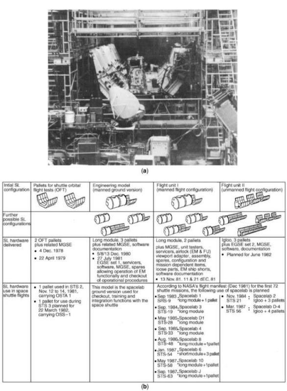
Figure 8. (a) Spacelab Integration Hall at ERNO. Bremen Assembly of the Spacelab Flight Unit II, comprising Pallets plus Igloo. The Igloo (secondary structure in tilted position and without cover) is attached to the pallets, which are partly equipped with cold plates and subsystem equipment. (b) Spacelab hardware content/deliveries/configurations and use in pre- and operational Space Shuttle flights.
Schedule and Cost
From fall 1969 to summer 1972, the ESA and the European space industry investigated their possible contribution to the U.S. Post Apollo Program proposed by President Nixon. The direct participation in the Orbiter development and the development of a Space Tug by the Europeans was not accepted, and in 1973, ESA and NASA signed the agreement for Spacelab. After competitive study phases A and B, the development proposals were submitted to ESA by two industrial teams on 14 April 1974. The final contract was awarded to the ERNO team of Bremen on 5 June 1974, which was the Authorization To Proceed (ATP). With a great number of industrial and governmental partners from both sides of the Atlantic involved, the following milestones were achieved:
24 June 1974 Kick off
11 November 1974 Preliminary requirements review (PRR) 19 June 1975 Systems requirements review (SRR)
29 September 1975 Contract signature ESA/ERNO in Paris
02 July 1976 Preliminary design review (PDR)
03 March 1978 Critical design review (CDR)
04 December 1978 Delivery of the first OFT flight pallet to KSC 28 November 1980 Spacelab engineering model rollout
30 November 1981 Spacelab flight module (FU-1) roll out 11 December 1981 Spacelab flight module delivered to KSC
05 February 1982 Spacelab (FU-1) acceptance at KSC
08 July 1982 Spacelab flight pallets (FU 2) delivered 13 January 1983 Spacelab design certification review at NASA HQ 18 November 1983 Final flight readiness review at NASA HQ 28 November 1983 First Spacelab flight with STS 9 “Columbia” 27 July 1984 Follow-on production unit delivery
More than 9 years after development began, Spacelab conducted its first flight. Although 3 years longer than originally assumed, this duration did not delay the Shuttle schedule. The launch date of STS-9 was well met by the completion of the development of the laboratory and by delivery of the first Spacelab payload (FSLP).
The participation of nine European countries in the Spacelab program meant that the development work was executed by companies that had nine different currencies. ESA used, therefore, a neutral artificial currency for this project; the accounting unit (AU) was a kind of provisional EURO, which corresponded to the U.S. dollar with a slightly changing rate of exchange over time. The baseline cost of 193 MAU (million accounting units) in 1974 increased by changes in the scope of the contract, cost overruns, and a 103% cost escalation during the 9 years to 579 MAU. Not including the escalation, the overall program cost was below 140% of the agreed cost for this first European manned spaceflight program. By the end of the program, Germany had contributed 56.79%,
Italy 11.34%, France 10.42%, the United Kingdom 6.67%, Belgium 5.29%, Spain 3.56%, the Netherlands 2.50%, Denmark 2.07%, Switzerland 1.07%, and Austria 0.29%. The Missions Spacelab was designed for a 10-year operational lifetime and/or 50 reflights. The laboratory exceeded its design lifetime by more than 4 years, but it did not achieve 50 flights. The first pallet flight occurred in November 1981, and the last in July 2001, a time span of almost 20 years. The first module flight took place in November 1983, and the last in April 1998, a time span of almost 15 years.
In total, 15 Shuttle flights carried a Spacelab module, 6 flights carried pallets plus an Igloo, and 10 flights carried pallets only (Tables 1 and 2). AN OFT pallet was used in the Orbiter “Columbia” to accommodate the Shuttle imaging radar SIR-A as early as the second flight. The third Shuttle flight STS-3 also contained a pallet in the payload bay.
The first flight mission of Spacelab SL-01 was the Shuttle flight STS-9, and the Orbiter “Columbia” was launched on 28 November 1983 from Kennedy Space Center Pad B at 332:16:00:00 GMT. The Spacelab consisted of a long module and a pallet whose total mass was 15,265 kg (33,252 lb), both up and down. The flight was scheduled for 9 days. However, NASA and ESA decided at midtime to prolong it by 1 day because the usage of the resources on board allowed such an extension. So the mission was completed when the Orbiter “Columbia” landed at Edwards Airforce Base in California on 8 December 1983 at 343:23:47:00, accomplishing a mission duration of 11 days, 7 hours, 47 minutes. In that time, the Orbiter rounded the globe 166 times and covered a distance of about 7.5 million kilometers at an inclination of 57° about the equator (Figs. 9 and 10).
The Spacelab mass was 12,780 kg (12,115 lb), of which 8145 kg (18,135 lb) were for the module and 3386 kg (7449 lb) for the pallet. The mass of the experiments and associated equipment was 3982 kg (8802 lb) and for the verification flight instrumentation 856 kg (2123 lb).
Spacelab 1 was a joint mission of ESA and NASA. Each agency sponsored about half of the scientific payload. In the United States, the Marshall Space Flight Center was assigned responsibility for the NASA sponsored portion of the payload. In Europe, the responsibility for the ESA sponsored portion of the pay-load, referred to as the first spacelab payload (FSLP), was entrusted to a technical management team known as Spacelab Payload Integration and Coordination in Europe (SPICE). This team was set up by ESA in 1976 at the German Aerospace Research Establishment (DFVLR), Cologne-Porz.
Spacelab 1 was a multidisciplinary mission of more than 70 experiments in five areas of scientific research: astronomy and solar physics, space plasma physics, atmospheric physics and Earth observations, life sciences, and material science. In total, 38 different facilities for these experiments existed. Of the 38 experiments, 16 required to conduct investigations were situated on the pallet and 20 in the module. Two of the 38 experiments had components both on the pallet and in the module.
Table 1. Spacelab Module Missions
| STS carrier | Launch date | Orbit incl. | Mission | Configuration | Discipline | European user | European | |
| & duration | & alt. | participation | astronant | |||||
| Major Partial | ||||||||
| STS 9 | 28 Nov. 83 | 57° | SL-01 | LM | f IP | Multidiscipl. | X | U. Merbold |
| Columbia | 10 days | 250 km | FSLP | |||||
| STS 51B | 29 Apr. 85 | 57° | SL-03 | LM | f MPESS | Mat. Science | ||
| Challenger | 7 days | 360 km | ||||||
| STS 51F | 29 Jul. 85 | 50° | SL-02 | IG + | 3P + IPS | Solar Astron. | X | |
| Challenger | 8 days | 320 km | ||||||
| STS 61A | 30 Oct. 85 | 57° | SL-D1 | LM | f MPESS | Mat. Science | X | R. Furrer E. Messerschmid W. Ockels |
| Challenger | 7 days | 330 km | Life Science | |||||
| STS 35 | 2 Dec. 90 | 28° | ASTRO-1 | IG + | 2P + IPS | Astronomy | ||
| Columbia | 9 days | 350 km | ||||||
| STS 40 | 5 Jun. 91 | 39° | SLS-01 | LM | Life Science | |||
| Columbia | 9 days | 300 km | ||||||
| STS 42 | 22 Jan. 92 | 57° | IML-01 | LM | Mat. Science | X | U. Merbold | |
| Discovery | 8 days | 300 km | Life Science | |||||
| STS 45 | 24 Mar. 92 | 57° | ATLAS-1 | IG + | 2P | Atm. Physics | X | D. Frimout |
| Atlantis | 9 days | 300 km | Solar Astron. | |||||
| STS 50 | 25 Jun. 92 | 28° | USML-01 | LM | f EDO | Mat. Science | ||
| Columbia | 14 days | 300 km | ||||||
| STS 47 | 12 Sep. 92 | 57° | SL-J | LM | Mat. Science | |||
| Endeavour | 8 days | 300 km | Life Science | |||||
| STS 56 | 8 Apr. 93 | 57° | ATLAS-2 | 1G4 | IP | Atm. Physics | X | |
| Discovery | 9 days | 300 km | ||||||
| STS 55 | 26 Apr. 93 | 28° | SL-D2 | LM | f uss | Multidiscipl. | X | M. Schlegel U. Walter |
| Columbia | 10 days | 300 km | ||||||
| STS 58 | 18 Oct. 93 | 39° | SLS-02 | LM | +- EDO | Life Science | ||
| Columbia | 14 days | 280 km | ||||||
| STS 65 | 8 Jul. 94 | 28° | IML-02 | LM | f EDO | Life Science X | ||
| Columbia | 15 days | 300 km | Mat. Science | |||||
| STS 66 | 3 Nov. 94 | 57° | ATLAS-3 | IG + | IP | Atm. Physics | X | Clervoy |
| Atlantis | 11 days | 300 km | ||||||
| STS 67 | 2 Mar. 95 | 28° | ASTRO-2 | IG + | 2P + EDO | Astronomy | ||
| Endeavour | 17 days | 350 km | ||||||
| STS 71 | 27 Jun. 95 | 52° | SL-M | LM | ||||
| Atlantis | 10 days | 300 km | ||||||
| STS 73 | 20 Oct. 95 | 39° | USML-02 | LM | f EDO | Mat. Science | X | |
| Columbia | 16 days | 300 km | ||||||
| STS 78 | 20 Jun. 96 | 39° | LMS | LM | f EDO | Life Science X | Favier | |
| Columbia | 17 days | 280 km | Mat. Science | |||||
| STS 83 | 4 Apr. 97 | 28° | MSL-01 | LM | f EDO | Mat. Science | X | |
| Colombia | 4 days | 300 km | ||||||
| STS 94 | 1 Jul. 97 | 28° | MSL-01R | LM | f EDO | Mat. Science | X | |
| Colombia | 16 days | 300 km | ||||||
| STS 90 | 2 Apr. 98 | 28° | NEURO-LAB | LM | + EDO | Life Science | X | |
| Columbia | 16 days | 300 km |
Table 2. Spacelab Pallet Missions
| STS carrier | Launch data | Spacelab pallet and purpose |
| and duration | ||
| STS-2 | 12 Nov. 81 | 1 Pallet/OSTA-01-Shuttle Imaging Radar SIR-A |
| Columbia | 2 days | |
| STS-3 | 22 Mar. 82 | 1 Pallet/OSS-01-NASA Office of Space Science |
| Columbia | 8 days | |
| STS-41G | 5 Oct. 84 | 1 Pallet/OSTA-03-Photographic and radar images of |
| Earth | ||
| Challenger | 8 days | |
| STS-51A | 8 Nov. 84 | 2 Pallets/Retrieval of Palapa and Westar communication |
| satellites | ||
| Discovery | 8 days | |
| STS-39 | 28 Apr. 91 | 1 Pallet/AFP-675-Air Force Program 675 |
| Discovery | 8 days | |
| STS-46 | 31 Jul. 92 | 1 Pallet/TSS-01-Tethered satellite |
| Atlantis | 8 days | |
| STS-59 | 9 Apr. 94 | 1 Pallet/SRL-01-Space Radar Laboratory |
| Endeavour | 11 days | |
| STS-64 | 9 Sept. 94 | 1 Pallet/LITE-Lidar In-Space Technology |
| Discovery | 11 days | |
| STS-68 | 30 Sept. 94 | 1 Pallet/SRL-02-Space Radar Laboratory |
| Endeavour | 11 days | |
| STS-75 | 22 Feb. 96 | 1 Pallet/TSS-1R-Tethered satellite reflight |
| Columbia | 16 days |
Some of the experiments on the pallet and in the module operated automatically; others were operated from the ground or by the crew remotely through the computer or by controls located on the instrument front panels. Other experiments in the module were operated directly by the crew.
Of the 38 experiments, 13 were sponsored by NASA, and 25 by ESA. Of the 13 NASA experiments, 5 were located on the pallet and 8 in the module. Of the 25 European experiments, 11 were situated on the pallet and 14 in the module. The 38 experiments on board Spacelab 1 were selected from more than 400 proposals solicited by NASA and ESA in 1976. The STS-9 Shuttle/Spacelab crew consisted of six astronauts, five Americans and with Ulf Merbold, one German. The Commander was the experienced 52-year-old John Young on his sixth space flight. The crew was divided into two teams, a red team and a blue team, both to work in space in 12-hour duty cycle shifts:
John W. Young Commander (CDR) Red Team
Brewster H. Shaw Pilot (PLT) Blue Team
Dr. Owen K. Garriott Mission Specialist (MS 1) Red Team
Dr. Robert A. R. Parker Mission Specialist (MS 2) Blue Team
Dr. Byron Lichtenberg Payload Specialist (PS 1) Red Team
Dr. Ulf Merbold Payload Specialist (PS 2) Blue Team
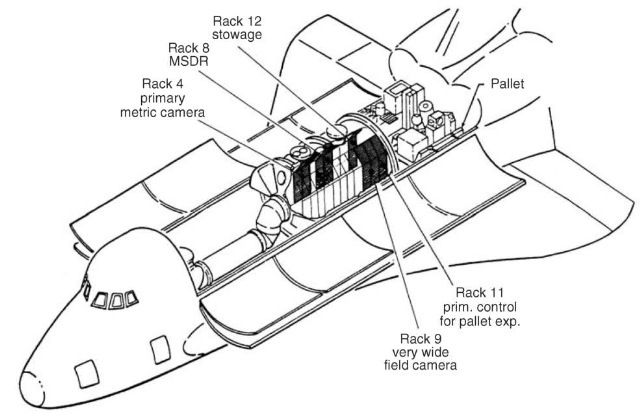
Figure 9. SL-1 configuration.
After the first Spacelab module flight SL-01, a second Spacelab mission, SL-02, with a pallet-only mode, including the Igloo and an instrument pointing system (IPS), was launched on 29 July 1985 and flown for 8 days. This mission specialized in solar astronomy. Both missions were joint NASA/ESA missions and were considered the conclusion of the development program.
After those missions, several other missions used Spacelab, both U.S. missions and international missions. With D-1 and D-2, Germany equipped two multidisciplinary Spacelab missions. Spacelab D-1 was launched on 30 October 1985 and was very successful. Spacelab D-2 was planned after the tragic “Challenger” mission in early 1986 and was delayed accordingly for more than 4 years until 26 April 1993.

Figure 10. Side view.
On 17 April 1998, the last Spacelab mission with a module took off into space with the Orbiter “Columbia” for a 16-day flight on a life science mission called NEUROLAB. This was 14 years and 5 months after its maiden flight in November 1983.
Lessons Learned
The Spacelab program was NASA’s largest international cooperation program, because it involved with ESA on the European side, nine countries and its major payload was developed, parallel in time to the Space Shuttle, a unique situation with respect to interdependences and interfaces. And for this situation, the partners had agreed to a ”no exchange of funds” funding and use of common hardware as much as possible. High hopes were attached to the Shuttle as the first recoverable launch system in the Post Apollo Program and its major payload Spacelab. For the European partner, however, Spacelab was the first manned space project ever.
Under these circumstances, the program was a full success. On the European side, the selection of an industrial prime contractor for the first time for a project of this size was a solution, which proved to be very helpful, because most of the coordination effort between companies from nine European countries was executed within the consortium under the leadership of the prime contractor.
The employment of U.S. industrial consultants in those areas that lacked experience in Europe, especially in the aspects of manned space flight, proved to be a very supportive measure. Representatives on all levels in the governmental organizations and in industry helped to avoid misunderstandings and served as on the spot mediators and real-time informants. A very tight network of clearly defined periodic meetings, working groups, and committees on all levels in government and industry kept all parties involved, provided the information to the need-to-know, and challenged the responsibilities in the decision-making process.
The intentional application of state-of-the-art technology for the Spacelab development reduced the risk and was an important factor in keeping the schedule and cost plan that had so many partners of different experience involved. The frequent usage of the laboratory for very different missions with short turnaround times required well-known technologies and easy access to spare parts. The access to Electric/Electronic Equipment (EEE) parts during a period of more than 9 years of development and 15 years of operation was, however, a problem. During this period of more than 24 years, the fast advance of technology in the EEE parts industry caused problems of an undisturbed supply of parts for Spacelab.
The availability of only one prototype of Spacelab, EM-1, in the program for cost saving reasons, resulted in the fact that there was no prototype in Europe to follow the operational program after EM-1 was delivered to the Marshall Space Flight Center in Huntsville, Alabama, on 28 November 1980.
After the infrastructural system of Shuttle/Spacelab was completed, the partners, NASA and ESA, and the participating countries in Europe did not continue their joint effort for using of Spacelab as the public would have expected. There was no agreed upon organization for evaluating the results achieved in the laboratory and their importance for science, technology, and application. Attention was directed too soon to the next generation of a manned space facility, the Space Station. The limited mission time of the Shuttle-attached Spacelab was one of the reasons for this development, although it took more than 10 years before the decision for the next generation of manned orbital infrastructure was made.
Fortunately, much of the good Spacelab experience could be saved and flow into the even greater challenge of a permanent, manned station in low Earth orbit launched with the Space Shuttle. Again, a module will be supplied by Europe incorporating Spacelab experience and spirit.
