Introduction
Sporadic attempts have been made for more than 150 years to use electrical energy to launch projectiles at high velocities. Throughout the world during the 1984. (The NASA nomenclature system for designating missions was changed starting with this mission, which was called STS 41-B, rather than STS-10.)
Mission 41-D, the twelfth mission, marked the introduction of the third Orbiter, Discovery, into the fleet on a 6-day satellite delivery flight launched on 30 August 1984. The fourth Orbiter, Atlantis, made its first flight in October 1985 carrying a Department of Defense payload as Mission STS 51-J, the twenty-first launch.
By the end of 1985, the STS had successfully accomplished 23 missions with a variety of mission objectives. The launch rate had increased with the addition of new Orbiters, from two in 1981, to three in 1982, to four in 1983, to five in 1984, and to nine in 1985. One successful mission had been flown in early January 1986, when disaster and tragedy struck the program with the destruction of Challenger soon after launch as Mission 51-L on 28 January 1986.
The Challenger loss, and the actions NASA took as a result, caused a significant hiatus in the launch of shuttles. The launch of Discovery on the STS-26 satellite delivery mission occurred more than 32 months later on 29 September 1988. (The nomenclature of missions had reverted to the former system.) By the time flights were resumed, several important policy changes had been made. No shuttle launches would be made at Vandenberg, commercial spacecraft would not be flown on shuttles, and no new DoD missions would be manifested on the Shuttle.
As a result, after resumption of flight, the launch rate did not continue to increase as had been planned, and the of nine per year has not been exceeded, even though an additional Orbiter, Endeavour, joined the fleet and made its first flight as STS-49 in September 1992. Parenthetically, the designation as STS-49 does not mean that it was the forty-ninth flight; STS numbers were now assigned with the manifesting of the mission, and the flights did not necessarily occur in that order. For instance, STS-28 was flown after STS-29 and STS-30, all in 1989. Shuttle Payload Processing. The Shuttle would carry two principal kinds of payloads reusable and attached like Spacelab and deployable, typified by communications satellites. Even that distinction is not absolute because the deployables require cradles, erection devices, and separation systems which were not deployed but remained in the payload bay and had to be removed before the next flight.
In the beginnings of the Shuttle program, the term “cargo” was frequently used to describe the complement of experiments, satellites, attached payloads, and airborne equipment used to elevate and separate deployable payloads carried on a given Shuttle flight. A payload could be either a part of the cargo or, in the case of Spacelab, possibly the entire cargo. Gradually, as the program matured, this distinction between cargo and payload became blurred and though there are still references to cargo, the terms tend to be essentially interchangeable, and the term payload is more common.
Spacelab, a so-called attached payload, was installed in the cargo bay and remained there throughout the mission. It could be flown in either a manned or unmanned configuration. In the manned configuration, it consisted of a pressurized module outfitted with experiments and connected with the crew compartment of the Orbiter by a tunnel. Once the Orbiter and Spacelab were in orbit, the mission and payload specialists could enter the Spacelab through the tunnel and perform the planned experiments; similarly when the flight was nearly complete, the Spacelab crew secured the experiments, left through the tunnel, and went last 20 years, most of the funding invested in electromagnetic (EM) launcher development has been for military applications. In most cases, the perceived advantage has been attaining higher velocities than can be achieved with propellant guns, leading to enhanced lethality. The elimination of gun propellants would also reduce vulnerability as well as allowing an increased number of stored rounds and enabling extended missions. The EM rail gun has been the preferred choice for this application because it has already repeatedly demonstrated muzzle velocities well above those of conventional guns—typically 2500 m/s versus 1750 m/s. The military challenge is to fit the electric pulsed power equipment into a battleworthy vehicle, especially if it needs to be compact. The main potential applications are direct fire tank guns, long-range artillery, and air and missile defense.
Several electrical or electromagnetic (EM) concepts have been suggested, as described later, but their potential for space applications is, as yet, limited. However, the technological bases are now being created on which future EM launch systems for space exploration could be based in the twenty-first century. Such systems could include launch to space from the surface of Earth, the Moon or asteroids, Maglev launch assist for large rocket systems and, possibly, EM thrusters for space transportation. Electrical ion engines have been used in space, and the Hall plasma thruster is under development for NASA.
The interest in electric launchers for military applications has led to improved understanding and advances in many technical areas. Most military applications for EM launchers require gigawatt power levels for pulse lengths of a few milliseconds to accelerate a useful projectile in a launcher of acceptable length. Coupled with the need for compact and robust equipment, this is a challenging goal for the pulsed power system. The desire to achieve muzzle velocities significantly greater than those of conventional guns—from 2-3 km/s —also requires developing the launcher and projectile. Recent progress in these areas could be the basis for future space applications.
History
There are isolated reports of efforts to develop EM propulsion technology in the nineteenth century, but the major developments were in the twentieth century. Pioneering efforts were undertaken in Norway in 1901-1903, in France during World War I, in the United States in the 1930s, and in Germany during World War II. In the second half of the twentieth century there were notable contributions from many countries, including Australia, Britain, China, France, Germany, Korea, Russia, the Ukraine, and especially the United States.
The first known scientific account of an EM launcher was provided by Prof. Page of the Colombian College, Washington, D.C., in 1845, only 10 years after Faraday’s pioneering studies on electricity (1). Page’s description of the electric launcher stated,
Another curious instrument is the galvanic or magnetic gun. Four or more (helical coils) arranged successively, constitute the barrel of the gun, which is mounted with a stock and breech. The (iron) bar slides freely through the (coils) and, by means of a wire attached to the end towards the breech of the gun, it makes and breaks the
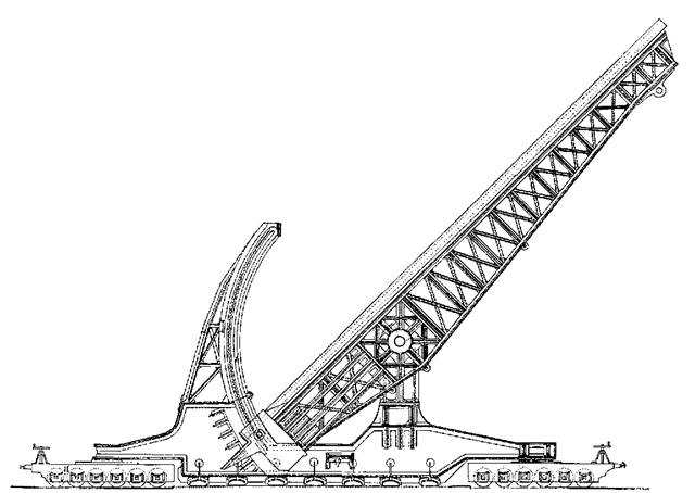
Figure 2. Fauchon-Villaplee’s long-range gun concept (ca. 1918).
• The force propelling the projectile is applied along the entire projectile, not just its base.
• The velocity and range of the projectile can be changed by varying the voltage without changing the angle of elevation of the barrel.
• There is no (powder) charge in electric guns, and there cannot be a premature explosion in the gun barrel.
• The power of electric guns… depends only on the instantaneous energy of the electrical source.
MacLaren’s U.S. patent of 1921 described a traveling magnetic wave induction launcher powered by a high-frequency, three-phase generator (5). In this, the traveling magnetic wave induced currents in the projectile and provided the EM force that accelerated the projectile through the barrel. In the 1930s, Professor Northrop undertook experiments at Princeton University with similar launchers powered by motor-generators and capacitors. The work was described in a novel written by Northrop1 (6) in which the theme was a journey to the Moon using an EM coil launcher in place of the conventional cannon proposed by Jules Verne. Northrop provided considerable detail on the engineering calculations, as well as several photographs illustrating the equipment needed—some of which were retouched to appear more impressive.
During World War II, a group led by in Germany was involved in developing EM launchers (7). The experiments started with induction launchers but because little success was achieved, refocused on rail guns. first rail launcher tests in September 1944 used an iron barrel similar to Fauchon-Villaplee’s that was energized by windings to create a transverse magnetic field to give the J x B forces needed for accelerating a projectile (Fig. 3). A velocity of 1080 m/s was achieved using a spring-loaded arrangement to ensure good electrical contact between the projectile fins and the rails. To meet the wartime needs of defending against high-altitude bombing raids, the development of a 40-mm EM gun with a high velocity (2000 m/s) and rate of fire of 72 rounds/min. was proposed. The initial design had a 10-meter iron barrel with a 3-tesla magnetic field. However, ler soon realized that the performance required could be achieved only with an air-cored barrel that had a much higher magnetic field, as shown in Fig. 4. This was designed, but not built, when the war ended. Modern EM rail-gun launchers are of this type, and operating currents are so high that pulsed magnetic fields > 20 T are generated, making the presence of iron irrelevant. Starting in May 1946, the Armour Research Foundation in the United States evaluated Hansler’s work. A comprehensive document was created based on reports, blueprints, and equipment from Germany (8). After evaluating the material and performing calculations, the report concluded that the anti-aircraft EM rail gun was technically feasible.
Relatively few efforts were undertaken in the aftermath of World War II, with one or two exceptions (9,10), until rail-gun experiments were undertaken at the Australian National University in the early 1970s based on the concept of macroparticle acceleration to high velocities for meteorite impact studies (11). These experiments led to a growth of interest in the United States and also caused non-US. efforts to accelerate. Most of these efforts were for defense applications, but launch-to-space was studied by MIT and NASA.
The early pioneers of electric gun research would be impressed to see what has been accomplished in the last decade. Pulsed power supplies using capacitors and rotating generators have provided currents in excess of 3 MA to EM rail launchers. Velocities of more than 6km/s have been achieved in rail guns using projectiles of a few grams, and muzzle energies of 5-8 MJ have been achieved for larger masses at velocities up to ~4km/s. Induction launcher technology has been demonstrated for low velocities (some 100′s m/s), but the highest confirmed velocity is 1 km/s.
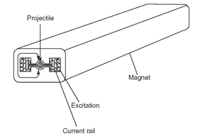
Figure 3. Sketch of Hansler’s iron-cored rail-gun (ca. 1944).
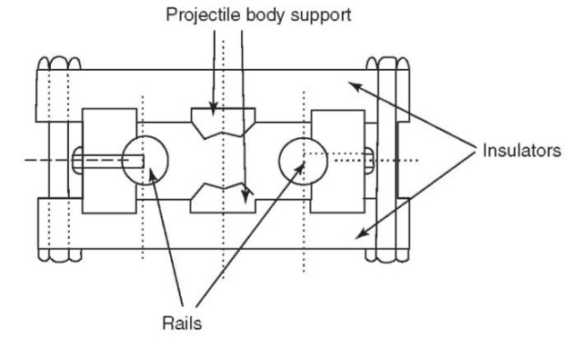
Figure 4. Hansler’s air-cored rail-gun cross section.
Electric Launcher Configurations
Rail Launcher Parameters. Rail launchers and coil launchers rely solely on electromagnetic (EM) forces to accelerate projectiles to high velocities. Most single-stage laboratory EM rail launchers operate at efficiencies of 30% or less, so that substantial energy is needed at the breech of the launcher for each shot. Modifications to improve launcher efficiency are described later. Some of these are more appropriate for launch-to-space than for ordnance applications.
Most experimental and theoretical studies of EM rail launchers during the last 20 years have used the simple air-cored rail-gun arrangement proposed by Hansler. In this, a short pulse of high-current electrical power is fed to the breech of a two-rail configuration in which the projectile is accelerated by the Lorentz (J x B) force (Fig. 5). This configuration has operated successfully across a wide range of conditions.
Because the induced magnetic field in the air-cored launcher bore is created by the current/passing through the rails, the JxB accelerating force (FEM) can be expressed as

where L’ is the inductance gradient (= dLldx) of the rails in the vicinity of the projectile. L’ is a relatively invariant quantity that depends on rail-gun bore geometry, more accurately, the relative fraction of the bore cross section occupied by the rails: a typical value is ~0.5uH/m. L’ is small, so a large current is required to accelerate a a significant mass m to a high velocity because

connection with several coils in succession and acquires such a velocity as to be projected to the distance of forty or fifty feet.
The well-known Norwegian inventor, Birkeland, developed an EM launcher using multiple coils (2). He obtained the first patent for an electric gun, formed a company to exploit the technology, and successfully tested two 4-m long induction launchers in 1902. However, his widely advertised public demonstration in 1903 spectacularly failed to live up to the claims that the projectile would be launched without flash or noise, and within weeks, he moved on, in this case successfully, to a different technical career.
Seeking a different approach, Fauchon-Villeplee started studies on EM rail launchers in France during World War I (3). In 1917, he successfully constructed a small working model powered by batteries. The principles of his direct current (dc) electric rail gun were different from those of the coil, or solenoid, launchers. A cross section of the basic configuration taken from one of his patents is shown in Fig. 1. The structure of the gun was iron, and it had two pole pieces to concentrate the magnetic flux into the region where the projectile was located. The magnetic field was energized by copper windings that extended along the length of the barrel and used the same current as fed into the fins of the projectile through sliding contacts. The lightweight projectile was a plastic tube that had a wooden tail in which copper fins transferred current via a sliding contact with the rails. Fauchon-Villaplee proposed that an EM cannon could be built to launch a mass of 100 kg at 1600 m/s. This formidable gun, shown mounted on a railway bogie in Fig. 2, was supposed to have a muzzle energy of 128 MJ—an energy level that has still not been achieved. When World War I ended, these projects were abandoned, but the work did not go unnoticed. A 1923 report by Korol’kov of Russia (4) critiqued the physics and engineering calculations of Fauchon-Villeplee and commented positively and negatively on the claimed advantages of electric guns:
• Electric guns fire without smoke and with virtually no noise.
• Electric gun efficiencies are considerably higher than those of conventional guns.
• Electrical guns use fuels whose energy is greater than explosives and are less expensive.
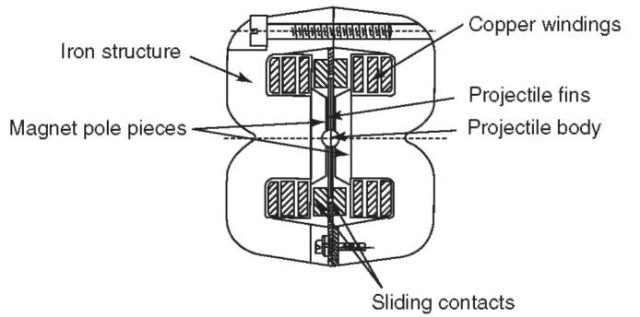
Figure 1. Cross section of Fauchon-Villaplee’s iron-cored rail gun barrel (ca. 1918).
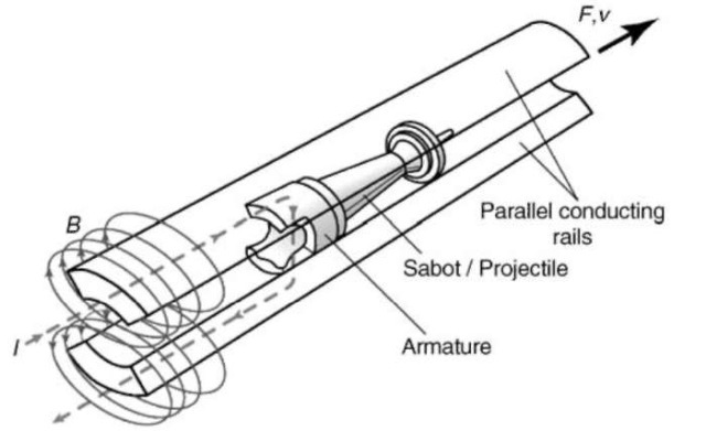
Figure 5. The two-rail, breech-fed rail-gun arrangement. This figure is available in full color at http://www.mrw.interscience.wiley.com/esst.
Currents of several megamperes have been successfully used in 90-mm bore rail guns in laboratory experiments.
Because the accelerating force depends on I2, it is independent of current direction and, in principle, an alternating current (ac) could be used. Some early systems were of this type, but shorter barrels and a better acceleration profile can be achieved by using a unipolar (dc) current pulse. Modern rail launchers use a current pulse that has a fast rise to a constant current for the majority of the acceleration, followed by a decrease in current near the muzzle exit to minimize muzzle flash. This “flattopped” pulse shape can be achieved using several short pulses in sequence from each section of a subdivided energy store or generator. Using this approach, the subpulses must be correctly timed and overlapped to achieve the desired total pulse shape (12).
One major source of inefficiency in the simple rail launcher is the magnetic energy remaining in the barrel at the instant of projectile launch. For an idealized constant current pulse, the inductive energy left in the barrel at launch equals the projectile muzzle energy so that the launcher efficiency2, even without other losses, cannot exceed 50%. Reducing the current at the muzzle exit decreases the magnetic energy stored in the barrel but increases the barrel length. The need for compact power supplies has led to the invention of alternative launcher configurations that may have higher efficiency, as described later. None of these has yet been widely studied, and further research is required to determine whether the advantages of these concepts outweigh their disadvantages.
Numerical models are used for the detailed design of EM rail launchers, but simple expressions can illustrate the fundamental principles and provide approximate engineering parameters, as shown here.
When the fundamental definitions of acceleration a and velocity v are integrated for the condition of constant acceleration a, they yield the well-known result that: “work done (or energy) equals force times distance.” For an EM
Table 1. Maximum Launch Energy (MJ) Achievable in a Simple Square Bore Rail Launcher
| Barrel length, m | Bore height, | mm | ||
| 80 | 100 | 120 | 140 | |
| 4 | 7.9 | 12.3 | 17.7 | 24.1 |
| 5 | 9.8 | 15.4 | 22.2 | 30.2 |
| 6 | 11.8 | 18.5 | 26.6 | 36.2 |
| GO | 15.8 | 24.6 | 35.4 | 48.2 |
| 10 | 19.7 | 30.8 | 44.3 | 60.3 |
Some techniques for increasing the achievable pressure have been sought, as described later, but they are still limited by Equation 8. Increasing / requires different rail materials, but the potential benefits of using high-temperature materials is largely offset by their poorer electrical and thermal properties, as can be seen from Table 2.
For example, although tungsten, has a melting point three times higher than copper, it will reach surface melting when / = 56 kA/mm, which is only a 37% improvement over copper. In the absence of fundamental material improvements, it may be necessary to use other rail launcher configurations that have higher U values, as described later.
Augmented Rail Launcher. In early concepts, external magnets—either superconducting (14) or permanent (15)—were proposed to provide a steady magnetic field that would permeate the entire launcher bore volume to add to the induced magnetic field produced by the applied current. However, such fields are generally small compared with the pulsed field resulting from the main current in large bore launchers, and this technique has now been replaced by additional rails close to the main launcher rails to enhance the magnetic field in the launcher bore. The augmenting rails may be energized either by (1) using all of the current that goes through the main rails, (2) using a separate supply, or (3) taking part of the main current and diverting it through the augmenting rails. The first option has generally been used experimentally because it is simple and only one power supply is needed.
Table 2. Limiting Rail Currents for Several Materials
| Rail material | /Lx, MA/m |
| Copper | 40.9 |
| Aluminum | 25.3 |
| Silver | 32.8 |
| Tungsten | 56.2 |
| Graphite | 35.0 |
| Stainless steel | 32.7 |
| Molybdenum | 45.5 |
| Elkonite (67% W, 33% Cu) | 65.5 |
The advantage of augmentation is that the current in the main rails and armature is reduced for a given accelerating force, thereby decreasing bore erosion and easing the task of the armature designer. In addition, the power supply can operate at lower current3. For single augmentation (one augmenting turn in addition to the rails in the barrel bore), L’~ 1 uH/m; double augmentation yields L’~ 1.2 to 1.3 uH/m. Singly and doubly augmented barrels have been successfully demonstrated with small-bore rail guns (16,17). Augmentation has not been widely considered for military applications because the launcher is larger and heavier than a simple barrel, complicated breech and muzzle current connections are needed, and additional magnetic energy is stored inductively in the barrel at the muzzle exit. However, this may not be a concern for a fixed launcher, as for a launch into space.
DES Rail Launcher. A second alternative to the simple rail gun is the distributed energy store (DES) launcher. In this, multiple power-feed points are located along the rails so that energy can be fed from several independent energy sources (18,19). This allows the maximum current to the projectile armature to be provided at just the right time in the acceleration process to maximize the EM force on the launch package.
To supply this launcher, the energy source4 needs to be segmented into separate sections that are energized sequentially as the projectile passes. The magnetic energy is switched into each stage of the launcher exactly when the projectile reaches that stage and is switched off after the projectile leaves. Therefore, the amount of inductive energy left in the barrel when the projectile leaves the muzzle is only that from the last one or two sections. If there are n sections, only ~ l/nth of the usual amount of inductive energy remains in the barrel, so that the overall launch efficiency is much improved. This concept may be especially advantageous for a long static system, such as for launch to space. For a military system in which it is necessary to slew the barrel rapidly, the need for multiple power leads to transfer current to each stage from many independent power supplies is a significant disadvantage.
Multirail Launcher. The third alternative version of the simple rail gun is the multiple rail arrangement (20). In this concept, the rails of the simple rail gun are subdivided, so that one-nth of the normal current passes through each rail. The rails are electrically insulated from each other and are electrically in series so that a low-current, high-voltage source can be used. The current required from the power supply is divided by the number of rails, but there is a corresponding increase in the applied voltage. Electrical shorting prevents this technique from being applied with plasma armatures, but it can be used with solid armatures if arcing contact between adjacent rails can be prevented. The concept has been demonstrated experimentally (21,22) but has received relatively little attention because of the concern about the ability to always prevent arcing. If arcing occurs between the rails or within the armature, the power supply could be electrically shorted out with disastrous consequences, unless precautions were taken. Staged Transiently Augmented Rail (STAR) Launcher. The STAR concept (23) combines the features of an augmenting magnetic field and the DES
launcher this can be written as

in which s is the launcher barrel length and F is the average EM force. Assuming that the force is constant across the cross-sectional area A of the barrel, the accelerating force is also

In EM launchers, as in propellant guns, the accelerating pressure p does not remain constant during the launch process, unless special design approaches are taken. The measure of how close the acceleration is to the ideal is the piezometric efficiency, t]P
![]()
For a propellant gun, t]P>2, but simple rail launchers have operated with ?7p~ 1.5, and operation to 1.3 or lower may be possible. Even lower values may be feasible with the “distributed” EM launchers described later. From Equations 3-5,

showing that, for a given barrel length and area, the muzzle energy is determined only by the average pressure p, or by the maximum pressure, pmax and the piezometric ratio.
Using / = Ilh as a measure of the linear current density on the inner surface of the rails that carry current (where h is the height of the rail at the inner bore from one insulator to the other), Equation 2 can be written as

Combining Equations 4 and 7 and using A = h2 for a square barrel yields

Typical values in this expression are L’ = 0.5uH/m and, for a copper rail, 7*~40kA/mm, to give (psq)max = 400 MPa. This is the highest pressure that a simple EM rail launcher can achieve. Substituting (psq)max in Equation 6 allows rail launcher parameters to be estimated.
For simplicity, the above analysis assumed a square rail launcher bore. Other geometries (e.g., rectangular or circular) have been investigated experimentally and analytically. Calculating U is complicated in complex barrel cross-sections and requires knowledge of the variation of current density and temperature around the periphery of the rail (13).
The maximum acceleration pressure achievable in a simple rail launcher is lower than the peak values achieved in powder guns, but useful performance levels can be still achieved with a rail launcher, even within these pressure constraints, as shown in Table 1. power feed. The augmenting field is provided by a series of independent coils that are energized only when the projectile is nearby. Figure 6 illustrates a three-section version of such a launcher; many such sections would be arranged in series for an Earth-to-space launcher. The energy used in these coils (less losses) is then transferred from coil-to-coil as the projectile accelerates along the barrel. The energy required for augmentation is therefore much less than in the usual augmentation concept. This arrangement allows the main rail current to be reduced, which is beneficial for the power supply and the barrel. The total launcher efficiency will also be better than that of the simple rail launcher because the augmentation is transferred forward with the projectile, rather than permeating the entire barrel structure. Although STAR is merely a concept at present, high-field pulsed magnets have been tested at magnetic fields up to 68 tesla (24)—a level that is significantly higher than that used in present EM launchers. The STAR concept is most appropriate for a long static system and is a possible candidate for launch to space.
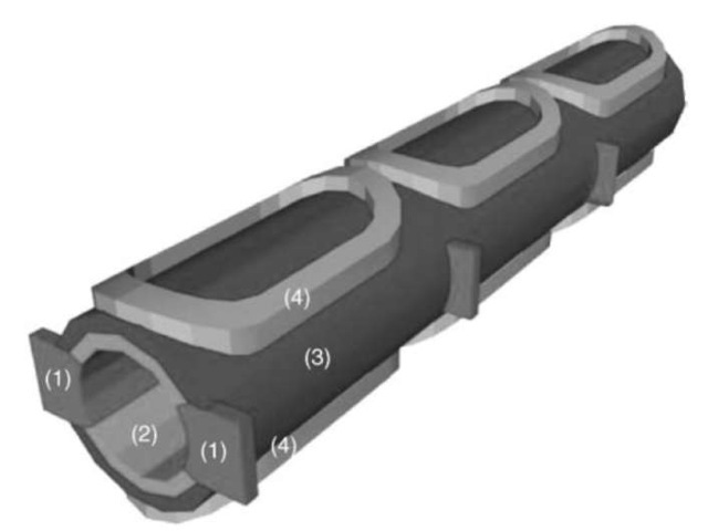
Figure 6. STAR—staged transiently augmented rail gun—module, showing the rails (1), insulator (2), containment (3), and pulsed augmenting magnet coils (4).
EM Induction Launchers. In principle, having no direct sliding contacts and operating with relatively low currents, EM induction launchers promise high efficiencies and contactless launch. Operating velocities of a few 100 m/s have been achieved by several groups, but there have only been two reports of velocities near or above 1000 m/s (25,26). As a consequence, there has been little funding for research on high-velocity launch applications, and this technology lags that of rail launchers. However, the approach may be useful for lower velocities and could replace the first stage of a rocket system.
Several induction launcher approaches have been studied (27). The barrel-type launcher consists of two parts —a stationary array of drive coils and a moving conductive projectile. The stationary coils generate a rapidly varying magnetic field that induces currents in the projectile. The interaction between the applied magnetic field and the induced magnetic field creates an axial propelling force and, in some configurations, a radial centering force that eliminates the need for a contacting guide rail system. The geometry can be coaxial or fiat channel, and the induction can be pulsed or traveling-wave. The fiat arrangement could be applied to the wings of a projectile in a toroidal configuration.
The single-stage pulsed induction launcher consists of a coaxial, single, fixed, drive coil and movable conduction ring. When the drive coil is pulsed with current ii, an induced current i<i is created in the conduction ring that generates a magnetic field in the direction opposite to that in the drive coil. The mutual repulsion between these two coils causes acceleration of the ring. The EM accelerating force is

where M is the mutual inductance and x the distance between the coils. High velocities and extremely high accelerations were reported with close-coupled, single-stage repulsion launchers of this type (28). A modified arrangement uses a smaller movable ring that can be nested inside the drive coil. This can be further modified by adding additional drive coils to create the barrel of a launcher that can be operated either synchronously or asynchronously. In the synchronous mode, only one drive coil is energized at a time and is synchronized by a feedback switching control system to match the movement of the accelerated coil or cylinder. The pulsed magnetic field from the driving coils induces an azimuthal magnetic field in the rear of the inner coil or cylinder in a direction that opposes the applied field, so that the inner coil is accelerated along the launcher. To maintain a unidirectional azimuthally induced current in the projectile, the current in all of the drive coils must be in the same direction. In strictly synchronous operation, the dc component of the current induced in the projectile decays with time, so that the direction of induced current flow has to be reversed.
Another system is the traveling wave induction launcher in which alternating currents are separately fed to a number of the drive coils across a region that is longer than the projectile being accelerated. This creates a traveling magnetic field that travels with a velocity v:

where 2t is the wavelength of the magnetic wave and f is the frequency of the current in the drive coils. The traveling wave induces azimuthal currents in the projectile and an associated magnetic field pattern that is similar to that generated by the drive coils. However, the induced magnetic field pattern is displaced relative to the driving field pattern, and the projectile is “dragged” along the barrel at a velocity close to that given by Equation 10. The advantages of this arrangement are that the propelling force acts more uniformly across the entire body of the projectile, a radial centering force acts to keep the projectile centered in the barrel, and the need for exact synchronization between the projectile and the drive coils is eliminated. Disadvantages include the need to divide the barrel into several sections that are fed with different frequencies so that the slip velocity and thermal losses can be minimized.
Energy Storage and Pulsed Power
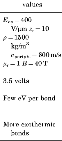
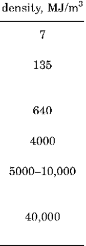
Energy Requirements and Options. From the earliest days of electric launcher research, it has been understood that supplying the required high-power pulses of electricity is a critical issue. Conventional guns and rockets have reached high level of capability after hundreds of years of development in which very energetic propellants have been created. Energy densities in propellants are impressively high—several MJ/kg. Achieving similar energy densities in a system that stores and transfers electrical energy is not yet possible, as can be seen from Table 3. Some of the other benefits of electrical systems such as higher velocities and improved safety due to the absence of propellants offset this disadvantage. In many situations, the capability to easily control the electric launcher to provide the required muzzle energy offers a benefit that is not available from conventional propellants.
The energy needed for an EM launcher is determined by the mission requirements. A notional set of input energy requirements for several launcher technologies for a muzzle energy of 20 MJ is given in Table 4. Other applications, such as an EM catapult for aircraft launch or launch to space, may require much more energy.
It is necessary to provide average power to the electrical system at a rate that matches the launch rate. The prime mover5 is typically coupled to a generator and operates through a transformer/rectifier to provide electrical power to the energy storage system. The availability of stored energy in a flywheel or battery pack can permit a few launches to occur quickly without energizing the main prime mover power system for certain applications. The design of this subsystem depends on the type of launcher and the firing rates required. For high firing rates or continuous operation, it is necessary to cool the components. Capacitor Banks. Most early electric launcher experiments used capacitor banks because they are inexpensive in small sizes and the components are widely
Table 3. Electrical Energy Storage Options
Table 5. Plastic Film Dielectrics
| Material | Dielectric constant | Breakdown voltage, V/\im | Stored energy Density, MJ/cum |
| Polypropylene Polyethylene Polyvinylidene fluoride Siloxane |
 |
 |
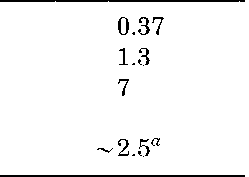 |
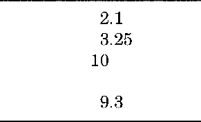
The capacitors in which energy is stored are the single largest contributor to the size and mass of the total system. The energy stored in a dielectric is proportional to the dielectric constant er and to the square of the operating electric field strength E%p, which is chosen as near as possible to the breakdown strength of the dielectric material while ensuring a low probability of spurious breakdown. Capacitors that use paper dielectric with foil electrodes were standard for many years. Plastic films such as polyethylene (PE), polypropylene (PP), and polyvinylidene fluoride (PVDF) provide better performance (see Table 5).
The performance of PE and PP capacitors is well characterized, and capacitors made from these materials are widely available. Units made from PVDF have been developed in the last decade. Although offering high energy density, this nonlinear material is more difficult to characterize, less efficient in operation, and more difficult to integrate into a complete system (31). As a result of these disadvantages, there is much to be gained if new dielectric materials could either be discovered or created. Recent small-scale experiments have been performed using siloxane-based materials with promising results (32). However, substantial investments are needed to bring a new capacitor material to reliable large-scale manufacture, and few sponsors have yet been found.
It is important to consider the entire capacitor system when component development is planned. If extremely high-energy-density dielectric materials were to become available, the volume of the system would then be dominated by other components, such as switches or inductors. Therefore, these components also need to be developed to reduce their size and weight. Integrated systems, in which component functions are combined, rather than by being individually optimized, may have significant benefits (33).
Rotating Machines—Homopolar Generators. Laboratory studies of electric launchers were undertaken in the 1970s and 1980s using homopolar generators (HPGs) which operated as electrified flywheels to deliver a low-voltage but high-current output (34). The HPG voltage, typically 100-200 V for an iron-cored machine, is much less than that required to drive an electric gun directly. Therefore, it is necessary to add a pulse compression stage in which energy is transferred into an inductor where it is temporarily stored as magnetic energy before delivery to the launcher at a higher voltage. Getting the energy into the inductor is relatively simple, but getting the energy out of the inductor to the gun can be difficult. An opening switch is needed that can carry a current of meg-amperes during inductor charging, but which can open quickly when transfer of available. Early experiments used banks with an oscillating output current whose characteristic time period was matched to the transit time of the projectile through the rail gun. Because this results in substantial current variation and very nonuniform acceleration, it is generally not preferred. In some cases, a high-frequency, rapidly ringing bank was used, and the averaged fluctuating current was accepted as an inexpensive way to undertake experiments. A better arrangement is to “crowbar” the circuit after the current has reached its peak value, which extends the high-current portion of the output pulse. To achieve this, a closing switch connects the current to the gun, and a diode is used in the crowbar leg with another closing switch.
Table 4. Input Energies Needed for 20-MJ Muzzle Energy
| Electric | Energy | Peak | Peak | Pulse | Minimum average |
| launcher | input per | current, kA | voltage, kV | length, ms | instantaneous power, |
| type | shot, MJ | GW | |||
| EM railgun | 40 | 4000 | 10 | 6 | 7 |
| ETC gun | 4 | 150 | 16 | 4 | 1 |
| ETC igniter | 0.4 | 50 | 10 | 1 | 0.4 |
Even when a single capacitor bank is “crowbarred,” current droop can cause inefficient energy transfer for a launch time that is longer than the characteristic decay time of the bank. The solution is to subdivide the capacitor bank into separate modules that can be independently triggered but are connected together at the current feed point into the launcher breech.6 A practical benefit of the modular approach is that repair and maintenance can be carried out on some modules while the remaining units continue to operate. The design of individual modules and the way in which they are connected depends on the type of gun and the duty required. A flat-topped current pulse can be created for a rail gun by triggering several modules sequentially to match the transit time of the projectile through the barrel. To get the desired high initial acceleration, a high-energy module is fired initially, followed by subsequent discharge of smaller modules. Because the projectile is traveling at higher velocity further down the barrel, later modules have smaller inductors in series with the capacitor modules to achieve faster rise times (12).
To ensure high efficiency, the output switches that connect the modules to a single load connection (the launcher breech) must prevent current from later modules from being routed back into modules that discharged earlier (29,30). If this is not done, considerable stored energy may be lost resistively, as it transfers from one module to another without ever reaching the launcher. Capacitor voltages are generally in the range of 10-15 kV, but values of 22, 44 kV, and higher have been used for some experiments. Such values necessitate close attention to insulation integrity and component locations to prevent electrical breakdown.
The current into the gun is required. Such switches are not readily available, although laboratory versions have been developed. The need for the opening switch and storage inductor has caused the HPG to go out of fashion during the last few years in favor of other rotating machines.
Pulsed Alternators. Synchronous ac generators of very large sizes (> 1400 MW) operate successfully for many years for electric utilities delivering voltages greater than required for most electric launchers. A short-circuit fault near the terminals of such a generator could cause a substantial overcurrent to flow and would damage the machine. To prevent this, utility generators are deliberately designed so that the resistance seen by such a fault (the “subtran-sient reactance”) is high enough to limit the current to a value that does not cause serious damage. However, such machines can be modified to deliver a limited number of higher than normal current pulses. For example, in 1963, a 3-GVA machine was used for testing circuit breakers with asymmetrical currents of 300 kA at 16.5 kV (35).
A pulsed alternator deliberately designed with a low subtransient reactance to deliver safely a high current is an alternative to the HPG for an electric launcher. Instantaneous power of several GW is typically needed for electric launchers, usually for subsecond pulse durations. Such a machine has to operate under conditions so extreme that they would be acceptable only once or twice in the lifetime of a utility machine.
Pulsed iron-cored machines are too heavy for many electric launcher applications. Therefore, during the last few years, the United States has invested in the development of pulsed alternators that have disk (36) and drum topologies (37,38). These machines can be driven up to full speed in seconds to minutes and then discharged into the electric launcher. Multipolar geometries are used to ensure compactness so that the ac output current has to be rectified for launchers that require dc. The rectifier and switching assembly can be a significant part of the total system mass, volume, and cost. High rotational speeds enable small machine sizes to be achieved but necessitate the use of lightweight, high-strength rotor materials in which the conductors necessary to carry current are embedded. Carbon fiber composites are the modern structural choice. At high rotational speeds, aerodynamic losses become important, and it may be necessary to partially evacuate the machine interior to minimize heating.
One feature shared by all rotating machines is their capability to store more energy inertially in the rotor than required for each shot. The voltage, power, and energy storage requirements need to be evaluated for each particular launcher type and mission to give the optimum design. In some cases, the machine size and geometry may be determined by the electrical design (required output voltage or power), but in other cases the stored energy is the dominant feature. Decoupling the design for electrical power production from the energy storage design may be possible by using flywheels that are separate from the power generator.
Linear Magnetic Flux Compressors. Linear flux compressors have been suggested as an alternative to rotating machines and capacitors for driving electric launchers (39). By using large quantities of high explosives to drive conductors together to compress a magnetic field, current pulses greater than 250 MA have been achieved in microsecond pulses at low efficiencies (< 1 to 10%).
Neither of these conditions is ideal for an electric launcher that might require pulses of a few milliseconds, especially because the use of explosives implies single-shot operation. Replacing explosives with a fuel/air combustion system has been suggested for multi-shot systems (40,41) but has not been tested. Flux compressor efficiencies are likely to fall to low levels as pulse lengths are extended, as a result of diffusion of the magnetic field into the conductors and correspondingly increased resistive losses.
Magnetohydrodynamic Generators. In a magnetohydrodynamic (MHD) generator, the flow of an electrically conducting gas (a “plasma”) through a magnetic field generates a voltage which, when extracted through electrodes in a generator channel, can transfer current to an external load without the intervention of any rotating element, such as a turbine or generator. A practical device consists of a plasma source and a channel, though which the plasma flows following acceleration in a supersonic nozzle, together with a magnet and electrodes embedded in the channel. The plasma is produced by reacting fuel and oxidant, together with “seeding” by a material of low ionization potential, such as a potassium or cesium compound. Early electric utility concepts also considered high-temperature, gas-cooled nuclear reactors cooled with cesium-seeded helium as the heat source. It is possible that a future space system could employ a similar Brayton or Rankine-cycle arrangement.
Considerable research was undertaken in the 1960s and 1970s on MHD devices for long-duration, low-current, utility power generation, but relatively little research has been done for pulse lengths of a few milliseconds. Repetitive, low-current (kA) pulses at a frequency of ~2Hz and rise/fall times of tens of milliseconds were generated for pulses of a few seconds during operation of a liquid oxidizer/solid fuel rocket-driven generator (42). Currents as low as this would need to be transformed up for most electric launcher applications. Explosively driven, highly ionized argon systems have produced extremely high power (>GW) and high current (>MA) for tens of microseconds (43).
The claimed advantage of MHD generators is the relative simplicity of their ”direct conversion” of thermal to electrical energy. However, the relatively low conductivity of most partially ionized plasmas limits the current that can be obtained from MHD generators to 10′s kA, rather than MA desired for large electric launchers. One experiment to power a low-current rail gun with a MHD generator via energy storage in an inductive current transformer has been reported (44).
Inductors. Pulsed inductors have been used for intermediate energy storage and as a pulse compression component in HPG-powered rail-gun systems (11,45,46). Any low-voltage source including batteries, can be used to provide current for the inductor. The inductor can be regarded as a pressure vessel for mechanical design purposes; the stored magnetic energy is given by

![]()
inductor is ideal for minimizing EM interference with external circuits caused by fringing magnetic fields. Shielded solenoids are a less expensive alternative that can also have low fringing fields.
For large EM launchers, the need to store and deliver tens of MJ at a few MA necessitates inductances L of a few uH. Using high currents, it is difficult to achieve system resistances R less than tens of uO with room temperature conductors, so that characteristic current decay times (t=L/R) are typically <0.1 s. This requires discharging the inductor very quickly after charging, otherwise substantial current decay and losses occur. It is helpful to cool the inductor to cryogenic or even superconducting temperatures, so that R is reduced and t increased. Cooling copper to liquid nitrogen temperatures (77 K) is beneficial in reducing resistance. Liquid hydrogen (20 K) with high purity (99.999% purity) aluminum is even better but requires careful handling. At liquid helium temperatures (4K), many materials become truly superconducting, and large inductors have been made with NbTi and NbSn3 conductors for nuclear fusion experiments. Liquid helium is unlikely to be acceptable on cost or logistic grounds for military applications but could be attractive for static ground-based systems that operate for long times with low losses.
The last decade has seen spectacular progress in high temperature superconductors based on copper oxide compounds: superconductivity has been demonstrated at temperatures well into the liquid N2 range (over 130 K). So far, critical current densities are low, and present conductors are not yet candidates for high-field inductors. Nevertheless, there are promising developments in the development of high current density (>1MA/cm2), YBaCuO films on flexible substrates that could be used for inductors, and further improvements seem likely (47). Batteries and Flywheels. The two options usually considered for energy storage are chemical batteries and flywheels. Batteries store large amounts of energy very compactly (a standard lead-acid automobile battery may contain 50 MJ) but cannot deliver high-power pulses. The recent international interest in developing electric vehicles for the consumer market is likely to lead to battery improvements. Unfortunately, electric vehicle requirements do not match the energy or pulse length needs of electric launchers. Modified batteries for high-power delivery generally use bipolar geometry, but even these are not well matched to most electric launcher requirements unless coupled with a multistage inductor (48). Lithium-ion battery technology has recently progressed rapidly, but other candidates are also possible. In all cases, batteries (and a similar system, the ultracapacitor) are based on electrochemical reactions that have characteristic voltages of 2-4 volts, so that multicell units are necessary to get voltages of 100-500 V. The voltages needed for electric launchers require multiple series/parallel strings or, more likely, electronic inverters to transform the battery dc output to high voltage dc.
Flywheel energy storage is another alternative. Very high energy storage densities can be achieved, especially at high peripheral rotor speeds. Oak Ridge National Laboratory has achieved peripheral speeds > 1400 m/s using carbon fiber composites (49). Less highly stressed versions of such flywheels are now in service commercially on a limited scale for passenger buses in Europe. There are significant differences between long-term energy storage and discharge for commercial applications versus the short pulses needed for electric launchers. The flywheel requires support subsystems for bearings, lubrication, and vacuum housing and needs to be coupled to a generator with a transformer/rectifier to produce high-voltage dc for launchers.
Auxiliaries. All of the power delivery and energy storage devices described here require auxiliary components. For example, switches are required to connect the pulsed power source to the electric launcher. These need to transfer high currents and to hold off high voltages. Options include solid-state devices, spark-gap switches, vacuum switches, and plasma-filled devices. Other auxiliaries depend on the specific power technology. For example, high-speed rotating generators require brushes and slip rings, vacuum enclosures, and cabling to connect the components together and to the gun breech. Operation of the entire launcher system requires a control system that includes the diagnostics necessary to monitor the total system health. This control system must integrate inputs from the prime power, pulsed energy and power system, launcher control system, and an overall mission control system.
Space Applications
First Stage/Orbiter Launch. A natural progression from the early work of Birkeland and Northrop was for low-velocity applications of launcher technology to merge with the development of linear induction motors. Linear motors are usually considered for continuous applications such as ”people movers” in transit systems or for intercity trains where magnetic levitation can be employed in ”maglev” systems. These motors operate continuously. A class of applications that has arisen recently is linear motors in amusement park rides in which short-term ”launches” of a few seconds provide passengers the ”thrill” of a high (or low)-g ride. An extension of this is to the launch of aircraft or other military equipment.
During World War II, a full-scale EM catapult called the ”Electropult” was developed and built by the Westinghouse Corporation for the assisted launch of U.S. bombers from short runways on small mid-ocean atolls in the Pacific (50). Although successful, the project was finished too late to enter the war and was not pursued further. Similar efforts have been restarted in the last few years by the U.S. Navy to develop an EM Aircraft Launcher System (EMALS) to replace the steam catapult on an aircraft carrier (51). Depending on the results during the next few years, it is possible that future aircraft catapults could be of this type. The masses launched in these systems are 5-50 tons, and the required velocity is usually 25-100 m/s, so that launch energies of 50-100 MJ are typical. The challenge in this case is to accomplish the launch in the limited distance onboard the aircraft carrier, which is about 100 meters. The aircraft is therefore subjected to an acceleration of about 3 gs. The most important system concern is reliability; failure rates need to be less than 1 in 10 million to be acceptable for naval aviation.
The NASA Space Flight Center in Huntsville is currently testing a small-scale system of this type that could form the basis for a future replacement of the first stage for an Earth-to-space orbiter launch system (52). This could eliminate the first stage of a multistage missile system by boosting the orbiter to the speed at which the later stages can be ignited for further propulsion. A system of this type, known as Maglifter, was proposed in 1994 (53). A similar proposal, made recently by the Russians, suggested the use of MHD generators to power the launcher (54). Based on the technical success of experimental maglev trains in Japan and Germany, the successful development of such a system seems quite feasible.
Direct Launch to Space. It is remarkable that one application that was apparently considered by the early developers of EM technology was that of launching manned or unmanned objects directly into space.7 The interest was based on the idea that, in principle, EM forces can act at very high speeds, so that there should not be any fundamental physical barriers to their operation. Though this is largely true, some physical effects have been encountered at speeds in excess of 3 km/s that are not yet fully understood, and the velocities required for a direct Earth-to-space launch have not yet been reached except with gram-sized projectiles.8
Two concepts have been studied—the coil-based inductive system and the rail-gun system. The earliest versions of coil launchers, referred to as ”mass drivers,” were studied at Princeton University by O’Neill and his colleagues (55,56) and at MIT in the late 1970s and early 1980s. Only relatively low velocities of (< 100 m/s) were achieved, but because O’Neill’s suggestion was to use the mass drivers for escape from the Moon or to move objects from one orbit to another, very high velocities were not necessary. What was important was the use of renewable energy—so that solar panels were proposed. Scientists at the Sandia National Laboratories, where velocities up to 1 km/s have been achieved with a coil system (25), have suggested launch-to-space using a coil gun (57), but the required muzzle velocity of 6 km/s has not been achieved. Rail guns have been much more successful in demonstrating high velocities (up to 4.3 km/s with 0.6 kg and ~ 7 km/s with gram-sized projectiles) and high energies (up to 9 MJ), and this has led to a number of detailed studies of possible space launch (58-65).
Very high energies and power levels are required to accelerate large masses into space. Launching a 1000-kg aeroshell of the type illustrated in Fig. 7 requires an armature and sabot system that may make the total mass 1250 kg (see Fig. 8). At a launch velocity of 7.5 km/s, this represents a muzzle energy of 35 GJ. One suggested approach would use a staged transiently augmented rail-gun (STAR) launcher of the type illustrated in Fig. 6 (65).
This concept offers very high efficiency because the energy needed for the launch is transferred from section to section along the launcher during acceleration. With a launcher efficiency of 80%, the energy input for the launch of this package would be 44 GJ. The cost of the electricity for such a launch would be negligible—less than $1000. A substantial capital investment would be required to build, install, and operate such a facility, including a dedicated power supply or link to the utility network. For a moderate peak acceleration (by gun standards) of 30,000 g’s, the launcher would be some 230 meters long while for 2000 g’s,it would be about 1 mile long.9 One recent estimate of the cost of such a system is about $1.4B (65) (see Table 6). A proposal for an induction launcher system also estimated a capital cost of $1-$2B. These costs are competitive with conventional launch methods and are similar to the cost of a single Shuttle-Orbiter vehicle.
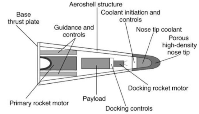
Figure 7. A flight body concept.
System needs have not yet been fully evaluated. One of the most important issues (for an Earth-based system) is the ”inverse reentry” problem of getting a gun-launched projectile up through the atmosphere without substantial ablation. Techniques for dealing with this, such as sacrificial ablative coatings or gas/ vapor nose-tip cooling, appear feasible at first analysis. A mitigating factor is that the projectile should transit the atmosphere in only a few seconds. Launching from an equatorial site at high altitudes, as shown conceptually in Fig. 9 (66), would be doubly beneficial because the atmospheric density would be lower and there is about a 400 m/s velocity contribution from Earth’s rotation.
Part of the total mass to be launched will be a rocket motor that is needed to circularize the orbit after reaching apogee (see Fig. 8). In addition, some divert capability may also be needed to ensure that the payload can reach a collection point in space, such as the International Space Station. As a result, only 20 to 30% of the aeroshell mass will be useful payload. Hence, if tens or hundreds of tons of supplies were to be launched in this way, many launches would be required. For example, to supply 100 tons of materiel into orbit in payload packages of 250 kg would require 400 launches per year, which is equivalent to two per day for 200 working days. Launching does not seem an impossible task (a power station of only about 10 MWe would be required), but management of the packages in orbit will require an infrastructure that does not presently exist. EM Spacecraft Propulsion. To reduce the mass of fuel that has to be carried by a rocket, it is beneficial to increase the exhaust velocity of the propellant. Chemical rockets generally operate with a specific impulse (1SP) in the range from about 250 to 400 seconds. To increase this, other techniques need to be developed. These include ion thrusters which have an 7SP~2000 to 3000 s,plasma thrusters, and even EM launchers. All of these are applicable only for use in space, not for launch into space from the surface of a planet.
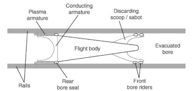
Figure 8. The launch package concept.
Two studies of EM launchers for spacecraft propulsion were published in the early 1980s. Snow, et al. evaluated an induction launcher (known as the ”mass driver”) as a reaction engine for LEO to GEO orbit transfers (67). The goal was an ISP of 500-1000 s, which requires an exhaust velocity of 5 to 10 km/s. As discussed earlier, induction launcher performance is far from this at present. Bauer et al. (68) proposed to use a rail gun that launched pellets of an unspecified material at velocities of 5 to 20 km/s, corresponding to an ISP of 500-2000 s. Apart from the failure of induction or rail launchers to reach the required velocities, a major concern with these concepts is the hazard created for other spacecraft, such as commercial satellites in near-Earth orbits, from ejecting high-velocity projectiles. In principle, these techniques could be considered for other missions, but there are competing technologies that are likely to be more attractive.
U.S. and International Programs
The best resources to consult for a review of EM launcher developments are the Proceedings of the EM Launcher Symposia that have been held every 2 or 3 years since 1982. These conferences have been published in archival form in special editions of the IEEE Transactions on Magnetics (69-78). Some papers can also be found in the nonarchival, but widely circulated, Proceedings of the Pulsed Power Conference, which is also now sponsored by the IEEE (79). Proceedings of specialized journal issues or conference in different countries are also available occasionally (80). Because of the defense-related nature of much of this work, as well as the desire of industrial companies to protect their proprietary concepts, it seems likely that much R&D has occurred that has not been openly published. This overview is based on information from open sources.
Table 6. Capital Cost Estimate for an Earth to Space EM Launcher
| Component | Cost per unit | No. units | Total component cost |
| Ac generators Switching Barrel Busbars and structure Civil engineering Total |
 |
 |
 |
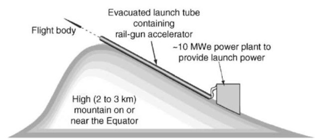
Figure 9. The preferred launch site layout.
United States. Although one or two isolated studies were undertaken in the late 1950s and 1960s, it was not until the mid-1970s that significant efforts began to develop in the United States. Following the approach pioneered at the Australian National University, several of these programs used homopolar generators as the energy and power source. These include facilities at Picatinny Arsenal (30 MJ), the University of Texas (60 MJ), and Eglin Air Force base (13 MJ). Large facilities were built with capacitors at Picatinny Arsenal (52 MJ) and Westinghouse (32 MJ). One facility installed by the USAF at Eglin used thousands of automotive batteries to charge an inductor that powered a rail gun. A larger number of small facilities were also used for R&D, based mostly on capacitors in independent modular arrangements. The largest rail guns used were 90-mm bore diameter and up to 8 meters long. Muzzle energies achieved with these rail guns were close to 9 MJ. In the last few years, financial strictures have forced rationalization of these facilities, and most have been dismantled or “mothballed.” Coil-gun research has been more sporadic; the last remaining organization that has interest in this area is Sandia National Laboratories, although this effort is now not active.
Europe. Efforts on EM launchers and related technology developments are being, or have been, undertaken in recent years in Britain, Germany, France, Italy, Sweden, Israel, the Netherlands, and Switzerland. Experimental facilities have been established in several locations; the largest are at Kirkcudbright in Scotland (33 MJ), Unterluss in Germany (30 MJ), and St. Louis in France (10 MJ). Smaller facilities are available in the other countries. Several of these facilities use power supplies based on capacitors that were supplied by U.S. manufacturers10. TNO in the Netherlands also used a refurbished U.S. homo-polar generator, and Magnet Motor GmbH in Germany is developing flywheel systems with permanent magnet generators that can serve as MW power sources to charge superconducting, inductive, pulsed GW systems. Research in Britain and France has been on rail guns and electro thermal chemical (ETC) guns. Germany, Israel, and Sweden have concentrated solely on ETC gun technology. The Former Soviet Union. During the latter years of the Soviet Union, considerable R&D was undertaken on EM launchers for military applications, although relatively little was published in the West. Russia and the Ukraine were the primary developers, and several significant systems were built. Perhaps because capacitor technology is less well advanced in these countries, greater use seems to have been made of rotating machines. One notable Ukranian system that was installed in a transportable trailer used four homopolar generators, powered by helicopter gas turbines, that had 60 MJ stored energy. Other rotating machine system designs were for even larger energies. Based on published reports, there appears to have been more emphasis on achieving very high velocities in Russian research than in the United States, with several reports of 6 or 7km/s with small pellets of a few grams (81) and possibly up to 10km/s with milligram masses.
East. One of the early efforts in developing rail guns was undertaken at the Ministry of Defense in Australia in the mid-1960s. The availability of a very large (550 MJ) homopolar generator at the Australian National University (ANU) and interest in the effects of micrometeorite damage on spacecraft led to a larger effort at ANU in the early 1970s. Experiments were undertaken at velocities close to 6 km/s with gram-sized projectiles. This work ended after the two main researchers moved to the United States in the late 1970s.
During the late 1980s and early 1990s, several programs on EM launchers were funded at a modest level by industrial companies in Japan. In most cases, capacitor banks were used that were purchased from U.S. companies. Several innovative solutions were developed with modest investments. In the related area of high-speed transport, Japan, like Germany, has strong research programs and a national commitment to improved high-speed transit technology. This could form a good foundation for induction launcher research for higher velocities.
Serious Chinese studies started in the late 1980s, but publication occurred only in Western conferences and journals in the mid-1990s. A wide range of technical interests and level of technical sophistication are evident in recent publications, that show interest in both EM and ETC technology. The work builds on what has been undertaken in the West but with its own variations. Summaries of Western work have been prepared by Chinese authors and are available as a foundation for further research (82).
South Korea began to take an interest in this technology in the mid-1990s, and there are now several technical organizations involved with their Ministry of Defense in this research, especially on ETC guns. A Korean Conference on this technology was held in 1997.
Future Possibilities
Despite the many potential advantages of EM propulsion enumerated by Fauc-hon-Villeplee more than 80 years ago, military applications of rail guns are not yet guaranteed. Further developments during the next few years will be important in showing what can be accomplished and where this technology should be best applied.
Much has been done in projectile, barrel, and power supply development for rail guns; velocities of 2000 to 3000 m/s are routinely reached with kilogram-sized projectiles and up to 7000 m/s with gram-sized masses. It seems likely that a research program on the technical challenges of rail guns for very high velocity applications, such as launch-to-space, would be most interesting and rewarding.
In contrast, much more has yet to be demonstrated before inductive launchers are likely to prove useful for high-velocity applications; the maximum velocity achieved so far is about 1000 m/s. The first use of induction technology seems likely to be for low-velocity applications; such as an EM catapult for the Navy. It is feasible that this could be followed by the replacement of the first stage of a launch system for an orbiter vehicle using the Maglifter (58) or a similar concept.

