Introduction
Work on the practical applications of artificial Earth satellites began in Russia (USSR) in 1961. The first of these satellites, the small low-altitude Strela series spacecraft of the ”electronic mail” type, were developed by the Scientific Production Association for Applied Mechanics (NPO PM) and placed in orbit in 1964. One year later, the Experimental Design Bureau-1 (OKB-1), (currently S.P Ko-rolev Energia Rocket and Space Corporation) inserted the active relay satellite Molniya-1 into a highly elliptical orbit. In 1965, work on this spacecraft was transferred to NPO PM and, for the next 30 years, this organization was the only one in the country developing telecommunication satellites (Table 1). The first geostationary satellite was inserted into orbit in 1975.
It was not until 1997 that a communication satellite, Kupon, developed by another organization, the S.A. Lavochkin NPO, was placed in orbit, and in 1999, the communication satellite Yamal developed by Energia was launched. At present, work to design communication satellites is being conducted by the Machine Building NPO and the M.V. Khrunichev State Space Scientific Production Center.
The spacecraft that were and are being developed in Russia may be divided into three categories on the basis of the types of orbit:
• satellites in low circular orbits, primarily at an altitude of 1500 km (such satellites are used to form multisatellite communications systems);
• Molniya type satellites in highly elliptical orbit;
• satellites in geostationary orbit.
Satellites in Low Orbit
The first launch of a Strela type satellite took place on 22 August 1964. This was the first spacecraft to enable exchange of information among remote users. The satellites were launched together, five to eight at a time, into a circular near-polar orbit an altitude of 1500 km. Each nonoriented small satellite had a mass of 50-80 kg and carried a retransmitter operating as part of an ”electronic mail” system and a command and instrumentation system that transmitted telemetry data to Earth on the status ofthe satellite’s onboard systems and received control commands from Earth.
The satellites’ electric power supply came from a system consisting of solar cells and storage batteries. The solar cells provided energy for spacecraft equipment during the illuminated part of the orbit, during which the storage battery was also charged. In the dark part of the orbit, the equipment operated on power from the storage battery.
Table 1. The Spacecraft Developed by NPO PM and the Dates of Their First Launch
| No. | Date | Satellite | Purpose(s) | Developer and manufacturer |
| 1 | 8/22/64 | Strela-1 | Data relay | NPO PM |
| 2 | 5/25/67 | Molniya | Telephone, television | OKB-1 |
| broadcast | (manufactured by | |||
| NPO PM) | ||||
| 3 | 7/2/69 | Molniya-1B | Telephone, television | NPO PM |
| broadcast | ||||
| 4 | 4/25/70 | Strela-1M | Data relay | NPO PM |
| 5 | 11/4/71 | Molniya-2 | Telephone, television | NPO PM |
| broadcast | ||||
| 6 | 11/21/74 | Molniya-3 | Telephone, television | NPO PM |
| broadcast | ||||
| 7 | 12/22/75 | Raduga | Telephone, television | NPO PM |
| broadcast | ||||
| 8 | 10/26/76 | Ekran | Television broadcast | NPO PM |
| 9 | 12/19/78 | Gorizont | Telephone, television | NPO PM |
| broadcast | ||||
| 10 | 12/17/81 | Radio | Data relay | NPO PM |
| 11 | 5/18/82 | Potok | Data relay | NPO PM |
| 12 | 4/22/83 | Molniya-1T | Telephone | NPO-PM |
| 13 | 10/25/85 | Luch | Data, telephone, | NPO PM |
| television broadcast | ||||
| 14 | 12/27/87 | Ekran-M | Television broadcast | NPO PM |
| 15 | 6/22/89 | Raduga-1 | Telephone | NPO PM |
| (manufactured by | ||||
| Polet PO) | ||||
| 16 | 7/13/92 | Gonets-D | Data relay | NPO PM |
| 17 | 1/20/94 | Gals | Telephone | NPO PM |
| 18 | 10/13/94 | Ekspress | Telephone, data relay | NPO PM |
| 19 | 10/11/95 | Luch-2 | Data relay, telephone, | NPO PM |
| television broadcast | ||||
| 20 | 2/19/96 | Gonets-D1 | Data relay | NPO PM |
| 21 | 3/12/00 | Ekspress-A | Telephone, television | NPO PM |
| broadcast | ||||
| 22 | 4/18/00 | Sesat | Telephone, television | NPO PM |
| broadcast | ||||
| 23 | 7/20/01 | Molniya-3K | Telephone | NPO-PM |
The spacecraft equipment used only a small amount of power, and, thus, emitted only small amounts of heat. Thus, a passive thermal regulation system was used to maintain the thermal conditions required for equipment operation. These conditions were maintained by selecting the optical coefficients of the spacecraft and instrument exterior on the basis of the heat flux from the Sun and Earth.
The spacecraft design consisted of two assemblies, a pressurized container for the equipment and the exterior of the solar panels, which was approximately spherical in shape.
The Gonets type of satellite marked a further development of data relay systems. These satellites were also launched in groups into circular orbit of an altitude of 1500 km and an inclination of 82.5°. The Gonets-D satellite was designed to relay data in digital form among users located in global service areas in two modes of operation:
• ”electronic mail”—with storage in the onboard memory and subsequent transmission to the user;
* real time, when the sender and recipient were in the radiovisibility area of the same satellite. Unlike Strela, the Gonets-D satellite had a magneto gravitational attitude control system, so that the long axis of the satellite was pointed at Earth with an error of 10°. The power supply system used both solar cells and a storage battery. The passive thermal control system consisted of heat pipes enabling removal of heat from the storage battery.
The main structural component uniting the blocks and assemblies of the spacecraft into a single system was the pressurized container. It served as the primary load-bearing element for connecting the spacecraft to the separation device by two brackets located diametrically on its cylindrical portion. The upper and lower frameworks for the solar cells were mounted on the upper end plate and cylindrical portion of the pressurized container, respectively. The lower framework was used as the mount for deployment of the antenna feeds and the magnetometer rods. The Gonets-Dl was launched on 2/19/96. This satellite was an updated version of the Gonets D, with an improved retransmitter to provide higher throughput. The major specifications of the Strela type (Fig. 1) and Gonets-Dl satellites (Fig. 2) are provided in Table 2.
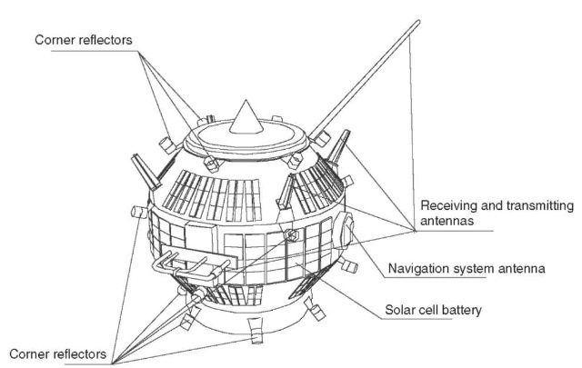
Figure 1. Strela type spacecraft.
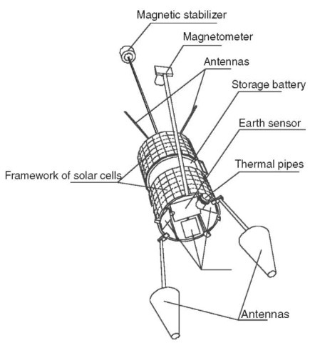
Figure 2. Gonets type spacecraft.
Satellites in Highly Elliptical Orbit
On 23 April 1965, the Molniya-1 satellite was launched, making it possible to establish communications among the most distant points in our nation. The introduction and use of this second-generation satellite enabled creation of the first national satellite communication system as well as distributed television broadcasting. One feature of the highly elliptical orbit is that, during the working phase, the spacecraft has radiovisibility of the entire territory of Russia (USSR).
Table 2. Specifications of Strela and Gonets-DI Satellites3
| Strela | Gonets-D1 | |
| Orbit | Circular, altitude 1500 km | Circular, altitude |
| and inclination of 85.5° | 1500 km and | |
| inclination of 82.5° | ||
| Retransmitter frequency range | P | P |
| Position in orbit | Not oriented | Uniaxial orientation |
| Area of solar array, m2 | 0.88 | 3.4 |
| Capacity of storage battery, A-h | 0.55 | 4 |
| Mean power of electric power | 12.5 | 100 |
| system per orbit, W | ||
| Type of thermal control system | Passive | Passive with heat pipes |
| Spacecraft mass, kg | 65 | 225 |
| Orbital insertion procedure | Multiple sats per launch, | Multiple sats per |
| 5-8 | launch, 6 |
The Molniya-1 was the first satellite launched into a highly elliptical orbit. The orbit had a perigee altitude of 460 km, an apogee of 40,000 km, and an inclination of 62.8°. There was a retransmitter on board, which received and transmitted digital and analog data in real time, and a control and instrumentation system for transmitting telemetry information to Earth on the status of onboard systems and receiving of commands from Earth. Telemetry sensors of signals and amplitude monitored retransmitter performance during routine use.
Molniya-1 consisted of a pressurized instrument container, two antenna blocks with directional antennas, solar panels, a thermal control system heat exchanger, and a cold gas control system. Inside the pressurized container was the instrument rack and its instruments. The pressurized container maintained the interior environment (temperature, humidity, pressure, and gas composition) and was the main load-bearing component of the structure.
To transmit a continuous signal to Earth the two antenna blocks were located in a single plane on opposite sides of the spacecraft. The antenna blocks were constantly pointed at the Earth using Earth-orientation sensors.
The spacecraft got its power from an electric power system consisting of a solar panel array and a storage battery. The solar array powered the satellite equipment during the illuminated part of the orbit, and during the dark parts, the storage battery was switched on. Having the panels of the solar array constantly pointed at the Sun provided the maximum possible energy. This was achieved by adjusting of orbital parameters with a cold gas system device. A station-keeping propulsion unit that had a liquid propellant engine was used to correct orbital parameters during insertion and maintenance in orbit.
A control system was used to hook up the electric power system to the onboard equipment and to control it, as well as the spacecraft systems. The control systems consisted of a control block, contact sensors, and separation switches. The control block’s function was to turn the power supply on and off, perform logic processing and distribution of individual commands from the control and instrumentation system, and also to support ground-based tests. The command segment controlling the operations of the attitude control and stabilization system, the relay station and all commands for the electric power and thermal control system were issued by the control and instrumentation system, bypassing the control block.
The contact sensors functioned to close electric circuits transmitting signals to deploy the structural elements of the antenna blocks and solar panels. The disconnect switches functioned to generate a ”disconnect switch” signal at the moment the device was disconnected.
The Molniya-1 equipment consumed a great deal of electricity and thus put out a great deal of heat. A multicomponent active thermal control system maintained the thermal conditions needed for the equipment to operate. This type of thermal control system maintained the temperatures of the attachment points for the apparatus mounted on the equipment rack within the pressurized container by a flow of liquid through pipes and adjustable electric heaters.
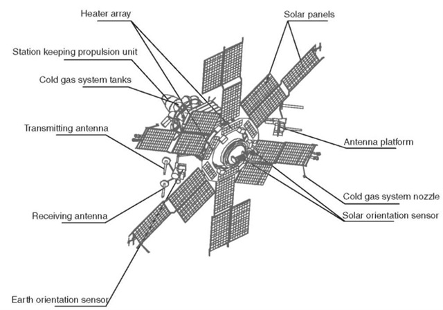
Figure 3. Molniya type spacecraft.
Using the Molniya-1 platform, the Molniya-1B was developed and launched in 1969, the Molniya-3 in 1971, and the Molniya-1 T in 1983. The structure and configuration of the spacecraft design was virtually unaltered; however, the active life of the equipment gradually increased as did channel capacity, increasing communications quality. The Molniya-3 K was launched in 2001 and has an active life span of up to 5 years. It has a new station-keeping propulsion unit, its temperature control system contains a new generation thermal regulator, new photovoltaics with improved performance have been installed on the solar panels, and the throughput capacity of the retransmitter has been improved (Fig. 3). The specifications of the Molniya type spacecraft are shown in Table 3. The Molniya launch vehicle was used to insert the spacecraft into orbit.
Table 3. Specifications of Molniya Spacecraft
| Orbit | Highly elliptical at an inclination of 62.8° |
| Retransmitter frequency range | C, P |
| Position in orbit | Dual-axial orientation |
| Area of solar array, m2 | 18 |
| Capacity of storage battery, A-h | 70 |
| Power of electric power system, W | 1400 |
| Type of thermal control system | Active |
| Spacecraft mass, kg | 1740 |
| Orbital insertion procedure | Single |
Spacecraft in Geostationary Orbit
The Raduga and Gorizont spacecraft were the first Russian communication satellites to operate in geostationary orbit (Fig. 4). They were designed to provide telecommunication services, including television, telephone connections, and data relay. The Gorizont, which is the most typical, was inserted into geostationary orbit by the Proton launch vehicle and the D or DM booster stage. An onboard propulsion system carried the spacecraft to the required longitude and maintained it there. Orbital inclination was not controlled. The first Gorizont spacecraft was launched on 19 December 1978, the last on 6 June 2000. During this period 33 satellites of this type were successfully, launched.
The introduction of Gorizont made possible a substantial (approximately by a factor of 10) increase in the channel capacity of satellite communications in the interests of the economy and international collaboration within the Orbita and Intersputnik systems. Moreover, Moscow, a new distributive television broadcasting system, and the Volna system of communications with commercial ships at sea were developed for use on these satellites. A multi-transponder onboard retransmitter was installed on this spacecraft. The total output power of the onboard transponders is 195 W. The Gorizont retransmitter comprises six C-band transponders, one Ku-band transponder and one L-band transponder. The C-band transponders are multipurpose and can be used for relaying television, multichannel telephone, and radio broadcast signals, and images of newspaper matrices. One of the transponders has enhanced output capacity and is designed for transmitting television signals to a network of simplified receiving stations using a highly directional onboard antenna. The L-band transponder has a crosslink with one of the C-band transponders that allow using it for communications between a ship station in the L-band and a shore station in the C-band. Reception and transmission of radio signals is handled by a set of 11 onboard antennas.
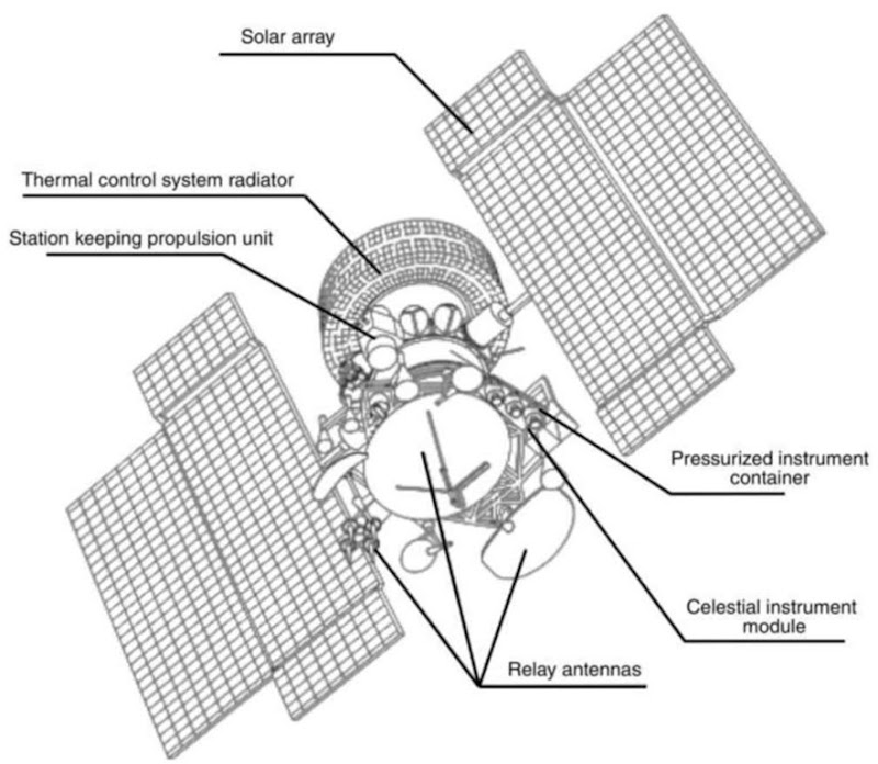
Figure 4. The Gorizont spacecraft.
The centimeter-band antennas provide various directional patterns and serve territories of various sizes on the Earth’s surface. Regions of heavy traffic are served by highly directional antenna, and those with less traffic by global antennas. The highly directional transmitting antenna used in the Moscow system is equipped with a special device that allows it to be reaimed once. This makes it possible to serve stipulated regions on the Earth’s surface in the event it became necessary to transfer the satellite from one spot in its orbit to another.
Despite the fact that Gorizont’s development began in mid-1975, the basic technical designs for the onboard utility systems used in its development are still being used in current projects. The spacecraft’s construction and configuration center around the pressurized instrument container. The instrument container is the main load-bearing component. It is used for mounting the structural units, instruments, and modules that comprise the satellite. The instrument container is a cylindrical pressurized module containing an instrument rack and components of the thermal control system. The interior of the container provides the most favorable climatic conditions for operating electronic instruments.
In orbit, the spacecraft is oriented so that the longitudinal axis of the instrument container, along which the onboard relay antennas are mounted, is constantly pointed at Earth, whereas the horizontal axes maintain a constant position in space. The station keeping propulsion units are located along the axis tangential to the orbit, and the axis that is binormal to the orbit corresponds to the axis of rotation of the solar panels. These panels are kept constantly pointed at the Sun by two one-stage electromechanical drives that rotate synchronously.
The spacecraft uses a triaxial attitude control and stabilization system. The sensor elements of the system include infrared Earth-orientation sensors, solar-orientation sensors, and gyroscopic angular velocity meters. The gyroscopic stabilizer and a cold gas engine act as servomechanisms. Analog devices control the system.
The orientation and stabilization system damps the movement of the satellite after it is separated from the booster stage and provides initial orientation to the Sun, initial orientation to Earth, and triaxial attitude control and stabilization of the satellite throughout its life in orbit with an error of ±(0.3-0.5)°.
The station-keeping propulsion units on the first Gorizont satellites utilized bipropellant liquid microthrusters that had a thrust of 45 g. The station-keeping propulsion unit had the form of two modules located so that the axes of the engine nozzles were pointed tangentially to the orbit on opposite sides. Given this configuration of the propulsion units, the onboard antennas could be pointed at
Earth without disruption, and thus it was not necessary to interrupt communication sessions when these units were on. The onboard spacecraft control system, along with a special module, controlled the propulsion unit. The station-keeping propulsion unit maintained the satellite within the stipulated longitudinal limits with an error no greater than 7 0.5°.
The spacecraft power supply system used a solar array with silicon photo-converters constantly pointed at the Sun, a cadmium nickel storage battery, and a voltage regulator that created optimum conditions for the common operation ofthe solar panels and storage batteries and stabilized the voltage in the range of (27 7 0.81) V. The capacitance of the storage battery provided enough electric power for the onboard equipment to support uninterrupted operation of the retransmitter while the satellite was in the dark portion of the orbit. The power of the Gorizont electric power system at the end of the satellite’s active life was 1280 W.
The solar array structure was redesigned to allow placing it in the limited volume of the launch vehicle nose cone during insertion into orbit. It had the form of two wings symmetrically located with respect to the instrument container. The wings were connected to electromechanical drives through articulated joints. Each wing consisted of four panels, the root, the end, and two side panels, which were connected to each other by intermediate joints. In the launch position, the wings were folded into a package and attached by special rods with a system of pins with mechanical locks that burst open after the spacecraft separated from the booster stage. The panels were rotated into operating position by spring-activated drives.
The temperature was maintained by an active, two-loop, gas-liquid thermal control system that consisted of a fan, a gas-liquid heat exchanger, a gas pipeline, a hydraulic pump, a thermoregulator, relief valves, a radiative heat exchanger, and a system control block. The required temperatures were maintained through forced gas circulation in the pressurized instrument container and forced coolant circulation through the satellite’s liquid loop.
The system control block provides automatic control of the system components and, if necessary, shifts from the main components of the system to the backup components. Pressure sensors, sensors of coolant pressure differential, and check valves maintain and monitor the state ofthe liquid loop. The system is guaranteed to maintain the temperature in the instrument container in the range of 0 to 40°C, and the magnitude of outgoing heat flux is up to 1400 W.
The onboard control unit controls operation of the onboard spacecraft systems. The control unit consists of the equipment of the command and instrumentation system, which receives control commands from Earth, generates a signal to allow the ground control systems to locate the satellite in orbit, and transmits telemetry information on the status of onboard systems and instruments; the telemetry monitoring equipment, which provides storage and output of data from the telemetry sensors of the onboard systems to the transmitting equipment of the command/instrumentation systems; and the control block, which provides strict logic for deploying the mechanical devices and distributing electric power and control commands among the spacecraft systems and instruments.
The Ekspress and Ekspress-A satellites represent further developments of Gorizont. The development of Ekspress made maximum use of the technical experience that had been accumulated in developing the Luch-2 and Gals spacecraft. Compared to its predecessors, Ekspress has significantly better technical and performance characteristics: 12 transponders for the onboard retransmitter; an improved station-keeping propulsion unit for maintaining orbital inclination, which was used for the first time on this satellite; improved precision for maintaining the satellite in orbit from 0.5° for longitude to 0.2° for longitude and latitude, and increased accuracy of spatial orientation of satellite axes in space up to 0.1 to 0.2°. With respect to design, Ekspress has the following distinguishing features, compared with Gorizont:
1. An information processing unit was added to the onboard control system for storage, maintenance, and transformation of control information to support satellite control, function, and onboard software. This software consists of a package of programs, which, in accordance with algorithms, receives information from the sensor systems, performs calculations, distributes the results, and controls the system or servomechanisms, or prepares information for other programs. The main equipment is the onboard digital computer. These control information processing and computing systems were first used on the Potok and Luch spacecraft.
2. The attitude control system has improved attitude control instruments, including a system of instruments that provides orientation to the North Star. Logic control over the system is the function of the control information processing and computing complex, which is part of the onboard control system. These measures increase the accuracy of the orientation of the
![]()
3. New, more effective types of station-keeping and attitude control engine units were adopted. As a result of the new task of correcting orbital inclination and the associated need to produce significant thrust, with limited mass resources available, Ekspress uses a station-keeping propulsion unit, including stationary plasma engines whose specific impulse characteristics exceed the analogous performance of other types of engines by an order of
![]()
unit mass to a minimum by using only a small quantity of working fluid— xenon—and a small number of tanks to store it. Propulsion units of this type were first used on the Potok satellite. For orientation, because of the relative frequency with which the engines have to be turned on, a propulsion unit using thermocatalytic engines of relatively high specific
![]()
4. The electric power system uses a storage battery with nickel hydrogen storage cells with high specific energy and efficiency characteristics compared to the cadmium nickel storage cells used on Gorizont.
5. Ekspress is similar in design to Gorizont, except for the location of the transmitters of the onboard retransmitter, which were removed from the pressurized instrument container and placed on the exterior framework where all of the onboard retransmission antennas are located.
A modification of this spacecraft—Ekspress-A—has 17 transponders and a 7-year active lifetime in orbit.
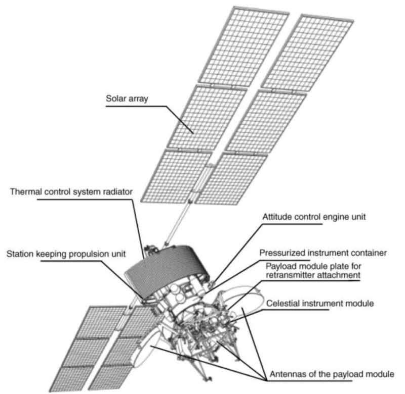
Figure 5. SESAT spacecraft.
Table 4. Specifications of Geostationary Spacecraft
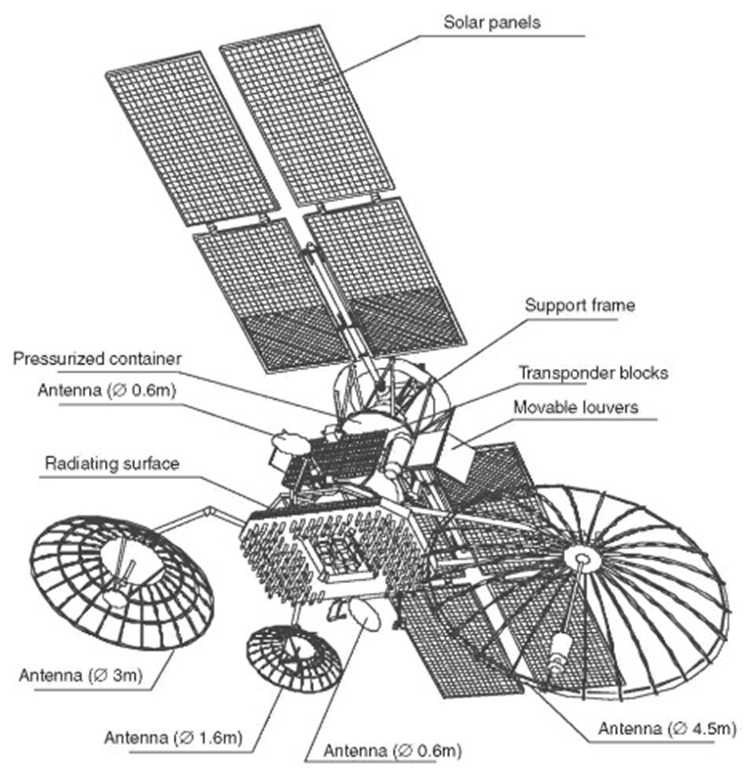
Figure 6. Luch spacecraft.
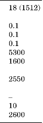
A further step in the development of telecommunication satellites in this series is the SESAT spacecraft, which has a 10-year active orbital life time and 18 transponders in the Ku-range (Fig. 5). The Proton launch vehicle is used to insert all these types of spacecraft into orbit. The major specifications of the geostationary spacecraft developed by NPO PM are provided in Table 4.
Table 5. Specifications for Luch Spacecraft
| Number of transponders Retransmitter frequency band Orientation precision, degrees Longitude hold, degrees Deviation in latitude, degrees Electric power, W Spacecraft mass, kg Active lifetime, years | 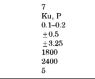 |
The geostationary satellites Luch are also telecommunication satellites developed by Russia. They are part of the satellite system of command and control of piloted and unpiloted spacecraft. Their development used technical designs validated on other spacecraft developed by NPO PM, such as Gorizont and Potok (Fig. 6). Their distinguishing feature is an antenna system with a high degree of transformability in the launch position, which is comprised of various different types of antennas. The electromechanical pointing system, which uses BCVM algorithms, makes it possible to track the user’s low-orbital spacecraft. The specifications of this spacecraft are provided in Table 5.


