Corporations are making greater use of wireless technologies for extending the reach of LANs where a wired infrastructure is absent, impractical, or too costly to install. Wireless bridges and routers can extend data communication between buildings in a campus environment or between buildings in a metropolitan area. A variety of technologies can extend the reach of LANs to remote locations, including microwave, laser, and spread spectrum. All rely on directional antennas at each end and a clear line of site between locations.
Wireless Bridges
Short-haul microwave bridges, for example, provide an economical alternative to leased lines or underground cabling. Because they operate over very short distances—less than a mile—and are less crowded, they are less stringently regulated and have the additional advantage of not requiring an FCC license.
The range of the bridge is determined by the type of directional antenna. A four-element antenna, for example, provides a wireless connection of up to one mile. A ten-element antenna provides a wireless connection of up to three miles.
Directional antennas require a clear line of sight. To ensure accurate alignment of the directional antennas at each end, menu-driven diagnostic software is used. Once the antennas are aligned and the system ID and channel are selected with the aid of configuration software, the system is operational. Front-panel LEDs provide a visual indication of link status and traffic activity. The bridge unit has a diagnostic port, allowing performance monitoring and troubleshooting through a locally attached terminal or remote computer connected via modem.
Because it is fully compatible with the IEEE 802.3 Ethernet standard, microwave bridges support all Ethernet functionality and applications without the need for special software or network configuration changes. For Ethernet connections, the interface between the microwave equipment and network is virtually identical to that between a LAN and any cable medium, where retiming devices and transceivers at each end of the cable combine to extend the Ethernet cable segments. Typically, microwave bridges support all Ethernet media types via AUI connectors for thick Ethernet (10Base5), 10Base2 connectors for thin Ethernet, and twisted pair connectors for 10BaseT Ethernet. These connections allow microwave bridges to function as an access point to wired LANs.
Like conventional Ethernet bridges, microwave bridges perform packet forwarding and filtering to reduce the amount of traffic over the wireless segment. The microwave bridges contain Ethernet address filter tables, which help to reduce the level of traffic through the system by passing only the Ethernet packets bound for an inter- or intrabuilding destination over the wireless link. Since the bridges are self-learning, the filter tables are automatically filled with Ethernet addresses as the bridge learns which devices reside on its side of the link. That way, Ethernet packets not destined for a remote address remain local. The table is dynamically updated to account for equipment added or deleted from the network. The size of the filter table can be 1,000 entries or more, depending on vendor.
With additional hardware, microwave bridges can pull double-duty as a backup to local T1/E1 facilities. When a facility degrades to a preestab-lished error-rate threshold or is knocked out of service entirely, the traffic can be switched over to a wireless link to avoid loss of data. When line quality improves or the facility is restored to service, the traffic is switched from the wireless link to the wireline link.
Wireless Routers
Wireless, remote-access routers scale wireless-connect, geographically disbursed LANs by creating a wireless WAN over which network traffic is routed at distances of 30 miles or more via microwave, laser, or spread-spectrum technology.
Applications of wireless routers include remote-site LAN connectivity and network service dissemination. Organizations with remote offices such as banks, health care networks, government agencies, schools, and other service organizations can connect their computing resources. Industrial and manufacturing companies can reliably and cost-effectively connect factories, warehouses, and research facilities. Network service providers can distribute Internet, VSAT, and other network services to their customers. Performance is comparable to commonly used wired WAN connections, approaching T1 speeds with a 1.3-Mbps data rate.
Unlike wireless bridges, which simply connect LAN segments into a single logical network, wireless routers function at the network layer with IP/IPX routing, permitting the network designer to build large, high-performance, manageable networks. Wireless routers are capable of supporting star, mesh, and point-to-point topologies that are implemented with efficient MAC protocols. These topologies can even be combined in an internetwork.
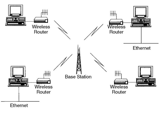
A polled protocol (star topology) provides efficient shared access to the channel even under heavy loading (Figure 133). In the star topology remote stations interconnect with the central base station and with other remote stations through the base station. Only one location needs a line of site to the remotes. Networks and workstations at each location tie into a common internetwork. The maximum range between the central base station and remote stations is approximately 15 miles.
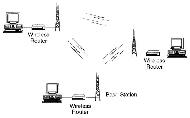
For small-scale networks, a CSMA/CA protocol supports a mesh topology (Figure 134). In the mesh topology, each site must have a line of sight to every other site. The CSMA/CA protocol ensures efficient sharing of the radio channel. The range with omnidirectional antennas is up to 3.5 miles.
Figure 133
Star topology of a router-based wireless WAN.
Figure 134
Mesh topology of a router-based wireless WAN.
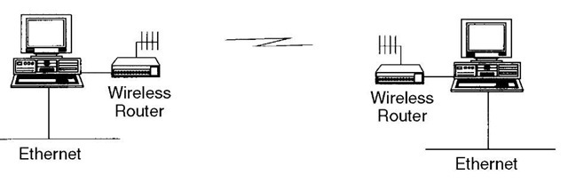
The point-to-point topology is useful where there are only a few sites (Figure 135). A router can also function as a repeater link between sites. The single-hop, node-to-node range is up to 30 miles, depending on factors such as terrain and antennas, with a multiple hop range extending up to a hundred miles. Clusters of nodes can also be connected using a point-to-point protocol for large-scale internetworks.
Network Management
In addition to the Windows-based tools for setting up and configuring wireless LANs, the Simple Network Management Protocol (SNMP) is available for managing wireless internetwork end to end. The same SNMP tools for managing the rest of the enterprise network can support the management of the bridges and routers on a wireless WAN. The result is a manageable network with reach extending to metropolitan, suburban, rural, remote, and isolated areas.
Figure 135
A point-to-point topology of a router-based wireless WAN.
SNMP is usually implemented with a vendor-supplied proxy agent. This is an application that continually polls the managed devices for changes in alarm and status information and updates its locally stored Management Information Base (MIB). Events such as major and minor alarms cause the device to generate enterprise-specific traps directed to the network management system (NMS). General alarm and status information stored in the MIB is made available to the NMS in response to SNMP’s Get and GetNext requests.
Last Word
Interconnecting LANs with bridges and routers that use wireless technologies is an economical alternative to leased lines and carrier-provided services. Installation, setup, and maintenance are fairly easy with the graphical management tools provided by vendors.


