6to4 Tunnel
The 6to4 tunnel, specified in RFC 3056, "Connection of IPv6 Domains via IPv4 Clouds," is an automatic tunneling mechanism, which is typically implemented on border routers. The 6to4 tunnel mechanism doesn’t require any explicit configuration and uses the IPv4 infrastructure like a virtual broadcast link. The tunnel destination is the embedded IPv4 address from the IPv6 destination address in the IPv6 header.
The IPv6 addresses, starting with the 2002::/16 prefix, are known as 6to4 addresses, so to construct the 48-bit 6to4 prefix, 2002 is prepended to the 32-bit IPv4 address for use by a host or a network behind it. For example, using a global IP address of 192.168.10.1 makes the corresponding 6to4 prefix 2002:C0A8:0A01::/48.
While encapsulating the IPv6 packet in an IPv4 packet, the 6to4 tunneling uses protocol number 41. The 6to4 tunneling mechanism provides two deployment scenarios:
■ Interconnecting 6to4 domains
■ Interconnecting 6to4 and native IPv6 domains using relay routers
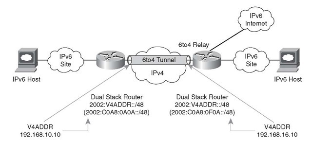
Figure 3-7 depicts the 6to4 deployment to interconnect 6to4 domains; this is the simplest deployment scenario to interconnect multiple IPv6 sites. In this deployment scenario, assign only one 6to4 address on the external interface of the router.
Figure 3-7 Interconnecting 6to4 Domains
The second deployment scenario becomes more prevalent when there is a need to communicate between the 6to4 domain and a native IPv6 domain. This communication requires the services of a relay router (which is a standard dual-stack router that uses both 6to4 and native IPv6 addressing). The relay router in Figure 3-8 connects to the IPv4 network, IPv6 native network, and 6to4 IPv6 site network.
Figure 3-8 Interconnecting 6to4 domain to native IPv6 domain
Figure 3-8 shows the interconnection of a 6to4 and a native IPv6 domain.
To make the routing work when interconnecting a 6to4 domain to a native IPv6 domain, an internal routing protocol like Enhanced IGRP (EIGRP) for IPv6 can be used for routing IPv6 within the site. Use a default route pointing to a specific relay router for communicating with the native IPv6 devices. Across the 6to4 tunnel, internal routing protocols cannot be run and the solution is limited to static or Border Gateway Protocol 4+ (BGP4+) routing. According to the specification, the 6to4 relay router must only advertise 2002::/16 and not any subdivisions. Any subdivision must be discarded; this will avoid polluting the IPv6 routing tables with small-prefix routing entries, helping to keep the routing table small.
Publically available 6to4 relays 2002:c058:6301:: (V4ADDR- 192.88.99.1) can be used; this is a special anycast address of the nearest relay router. This address should be used if IPv6 Internet access is desired. Because of the insecure nature of the tunnel between a 6to4 router and a 6to4 relay route, some of the security issues that exist are as follows:
■ The data contained in the packets is not checked by the 6to4 relay routers.
■ Address spoofing is a major issue, and the IPv6 address of the source can be easily spoofed.
Intra-Site Automatic Tunnel Addressing Protocol (ISATAP)
ISATAP, defined in RFC 5214, is an automatic overlay tunneling mechanism that enables communications among IPv6 hosts within a site. ISATAP uses the underlying IPv4 infrastructure as a nonbroadcast multiple access (NBMA) link layer.
ISATAP tunnels embed the IPv4 address of the interface in the last 32 bits of the IPv6 address. ISATAP tunneling transports IPv6 datagrams at a site where an underlying IPv6 network is not available and where there are a sparse number of dual-stack-enabled hosts that need IPv6 connectivity. To support automatic configuration to the network clients, the ISATAP routers provide network configuration support for the ISATAP site. This enables the IPv6 clients to automatically configure themselves.
As shown in Figure 3-9, the ISATAP address consists of three parts:
|
Top 64 Bits |
32 Bits |
32 Bits |
|
Global IPv6 Prefix or Link Local |
0000:5EFE |
IPv4 Address of the Interface |
Figure 3-9 ISATAP Address Format
■ The first 64 bits are either a link-local or global IPv6 prefix.
■ The middle 32 bits are 0000:5EFE (0200:5EFE if using public unicast IPv4 addresses).
■ The lowest 32 bits consist of the IPv4 address of the interface identifier.
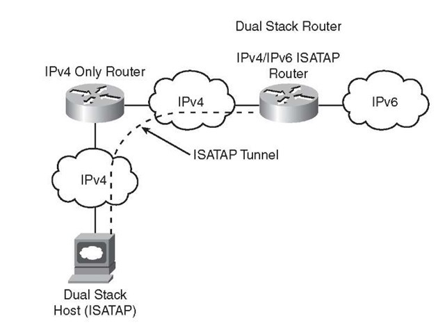
Figure 3-10 depicts the creation of an ISATAP tunnel by the dual-stack IPv6 hosts with the ISATAP router.
Figure 3-10 ISATAP Tunnels IPv6 over MPLS
While the service providers/large enterprises slowly move their infrastructure to support IPv6, they can use their existing IPv4 MPLS infrastructure to transport IPv6. In this scenario, the provider edge (PE) routers have the IPv6 routing capability, but the provider (P) routers have no IPv6 routing functionality enabled. This enables the service providers to provide IPv6 services (connectivity between the isolated IPv6 domains) without upgrading their backbone networks.
In the following section, you consider the following three concepts to transport IPv6 over MPLS:
■ IPv6 over circuit transport over MPLS
■ IPv6 using IPv4 tunnels over customer edge (CE) routers
■ IPv6 MPLS with IPv4-based core (6PE/6VPE)
Table 3-2 compares these three methods.
IPv6 over Circuit Transport over MPLS
Because the emulation of the circuit is at Layer 2, the underlying circuit transport is fully transparent to IPv6 (Any Transport over MPLS [AToM]). This methodology doesn’t need any configuration change at the PE or CE router.
Table 3-2 IPv6 over MPLS
|
Method |
Description |
Limitations (if any) |
|
IPv6 over circuit transport over MPLS |
Service provider (SP) with circuit to CE (fo example, Frame Relay or ATM). |
rScalability. |
|
IPv6 using IPv4 tunnels over CE routers |
This is a tunnel-in-tunnel approach and requires CE routers to be dual-stack enabled. No impact on the MPLS infrastructure. IPv6 traffic is encapsulated twice: first in the IPv4 packet and then into an MPLS frame. |
Tunnel overhead. |
|
IPv6 MPLS with IPv4-based core (6PE/6VPE) |
Standards-based: RFC 4659, 6VPE RFC 4798, 6PE The service is provided over the existing IPv4 MPLS service. Only the PE routers are impacted. |
Complexity. MPLS core doesn’t know about IPv6. Hard to troubleshoot. |
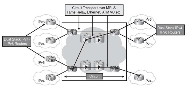
Figure 3-11 shows the IPv6 over circuit transport over MPLS.
Figure 3-11 IPv6 over Circuit Transport over MPLS
AToM can provide both leased line and Layer 2 service emulation such as ATM, Frame Relay, and PPP Ethernet. The only limitation of this approach is scalability—with an increase in CE routers, there will also be an increase in the number of tunnels. If the customer is not worried about the suboptimal routing, the scalability can be overcome by using hubs leading to a partial mesh.
IPv6 Using IPv4 Tunnels on Customer Edge (CE) Routers
With MPLS in the service provider core network, this is a tunnel-in-tunnel approach and requires CE routers to be dual-stack enabled. From the forwarding plane perspective, the IPv6 traffic is encapsulated twice: first in the IPv4 packet and then into an MPLS frame. For the service provider, this approach doesn’t impact the operation or infrastructure, so no configuration changes are required to the core or provider edge routers, making this approach simple. However, this design comes with its own scaling limitations because it involves manual configuration and the deployment of a mesh topology at the CE routers.
Figure 3-12 shows IPv6 using IPv4 tunnels on CE routers.
Figure 3-12 IPv6 Using IPv4 Tunnels on CE Routers
IPv6 MPLS with IPv4-Based Core (6PE/6VPE)
The following sections deal with the connection between IPv6 sites using 6PE (IPv6 provider edge over MPLS) and 6VPE (IPv6 VPN provider edge) for the MPLS VPN customers.
IPv6 Provider Edge over MPLS (6PE)
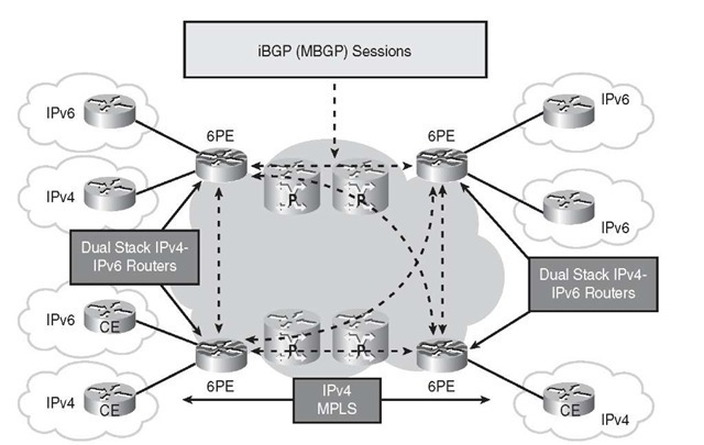
6PE is the Cisco implementation of the IPv6 provider edge router over MPLS. 6PE enables the IPv6 sites to communicate with each other using MPLS label switched paths (LSP) over the MPLS IPv4 core network. This feature requires MBGP (Multiprotocol Border Gateway Protocol) extensions on the PE routers to exchange the IPv6 reachability information for the IPv6 prefixes. The PE routers, being dual-stack, can now use the reachability information to apply the appropriate label. Because of the decoupling of the Control Plane and Data Plane in MPLS, it provides this interesting alternative to the transition of IPv4 and IPv6 over a single infrastructure.
On the ingress PE router, the incoming datagrams have two labels. The inner label is assigned to the destination IPv6 prefix through MP-BGP, whereas the outer label is based on the IPv4 address of the PE router providing reachability to the destination IPv6 prefix.
In Figure 3-13, the PEs are dual-stack routers with appropriate configuration of Label Distribution Protocol (LDP) and MBGP. Resource Reservation Protocol (RSVP) is used if MPLS traffic engineering is needed. All PE and core routers are configured with a common interior gateway protocol (IGP).
Figure 3-13 6PE
IPv6 VPN Provider Edge (6VPE)
6VPE, as specified in RFC 4659, "BGP-MPLS IP Virtual Private Network (VPN) Extension for IPv6 VPN," is for VPN customers. The IPv6 VPN service is the same as the MPLS IPv4 VPN service. This transition mechanism enables services such as "IPv6 VPN access," one carrier supporting other carriers, and so on.
The Cisco 6VPE implementation provides scalability with no IPv6 addressing restriction. This mode is similar to the IPv4 MPLS VPNs, so it enables the enterprises and service providers to deploy the IPv6 MPLS VPN service over their existing IPv4 backbone by just upgrading the PE router to the dual-stack-capable software.
Figure 3-14 shows the 6VPE.
Figure 3-14 6VPE


