Tweak Fill shader
The nice thing about fill shaders is that you can adjust them using IPR:
Random Note
Do you know when I first saw IPR? It was the coolest thing back in 1992. It saves you time. Make sure you utilize it. It traveled a long way to get here.
1. Click on the IPR button, either in the render window that you have open or at the top status line.
2. When the render has completed, follow the directions found in yellow at the bottom: “Select a region to begin tuning."
FIGURE 3.12 Use the IPR render view to quickly tweak your fill shader.
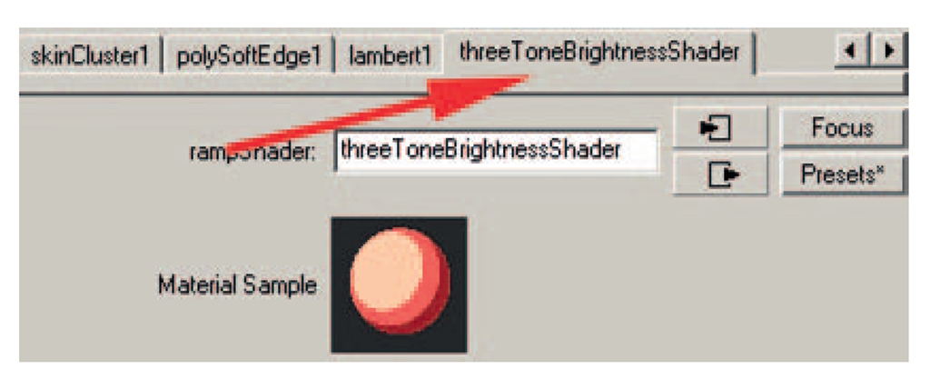
3. Select the geometry in the Attribute Editor (CNTRL + A), and scroll through the tabs until you find the threeToneBright-nessShader tab.
FIGURE 3.13 The threeToneBrightnessShader tab.
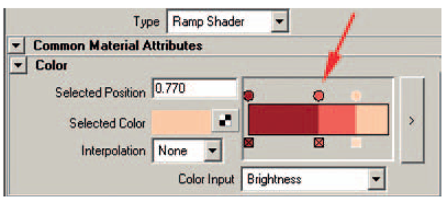
4. The three-tone brightness shader is a ramp shader. You can click and drag on the small circles to adjust the threshold that the colors show up in. The rightmost color is the color that shows up where the light is the strongest. The leftmost color shows up where the light is the weakest.
FIGURE 3.14 Ramp shader with three colors.
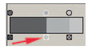
5. Create a dark gray for the left color and a light gray for the right color. Let’s find a midrange color. Delete the middle color by clicking on the X.
FIGURE 3.15 Delete the middle color.
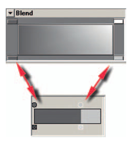
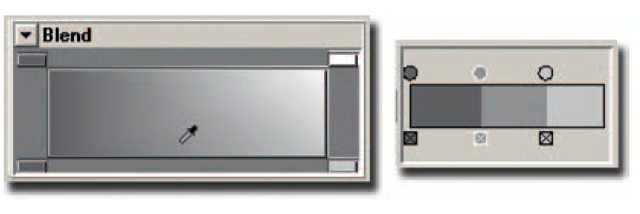
6. Click on the Selected Color chip and a Color Chooser window will open. In that window, open the Blend tab.
7. In the blend tab, if you click on any of the four rectangles it will load the current color. Load in the light and dark colors from the ramp. (Remember, selecting the circle on the ramp selects the color.)
FIGURE 3.16 Add colors into the Blend tab.
8. Click on the ramp between the two colors and that will add a third color circle.
9. In the Color Chooser window, select the eyedropper tool and choose a color from the blend area. For me, this saves a lot of time by allowing me to use the blend feature to get something closer that I can work with.
FIGURE 3.17 Third color chosen with the eyedropper tool.
10. Click Accept to close the Color Chooser window.
This looks like a good place to save. Our completed file is saved at Robby_3DLeads2D_4.mb.
Toon Line
The next step is to put on a toon line that matches the 2D character’s cleaned-up line.
Open the file
Open the animation file that you saved or our file Robby_ 3DLeads2D_4.mb.
Toon Line shader
The geometry should still be selectable from earlier in the lesson when we applied the toon fill:
1. Select the robot’s GEO node in the outliner, or click on the geometry and click the up arrow key on the keyboard. (The robot should be highlighted green.)
2. In the Rendering area, select Toon > Assign Outline> Add New Toon Outline Line Width = 0.058 or something smaller. (Don’t go too small; we’re about to adjust this line some more.)
3. Scroll down and open the section for Curvature Based Width Scaling; this will allow us to adjust the thickness of curved lines versus straight lines.
4. Turn on the check box for Curvature Modulation. (Where’s the little green Marvin Martian? Give me the Q-36 Explosive Space Modulator.) You might have to adjust your global line width to make your lines visible again.
5. I find it hard to see the toon lines in the perspective window when they are highlighted in green. So in the camera view you can select Show > Selection Highlighting to hide the highlighting.
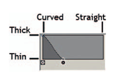
Let’s look at that curvature width ramp. What happens when you move the curve? It might take a little bit to figure it out. It looks like the documentation has the explanation backward (I might be reading it wrong). Here is how I see it working:
FIGURE 3.18 Curvature width.
1. [Left] Moving the curve to the left side of the ramp affects the toon lines that are curved.
2. [Right] Moving the curve to the right side of the ramp affects the toon lines that are straight.
3. [Top] Moving the curve to the top of the ramp makes the toon lines thicker.
4. [Bottom] Moving the curve to the bottom of the ramp makes the toon lines thinner.
FIGURE 3.19 Curvature width ramp.
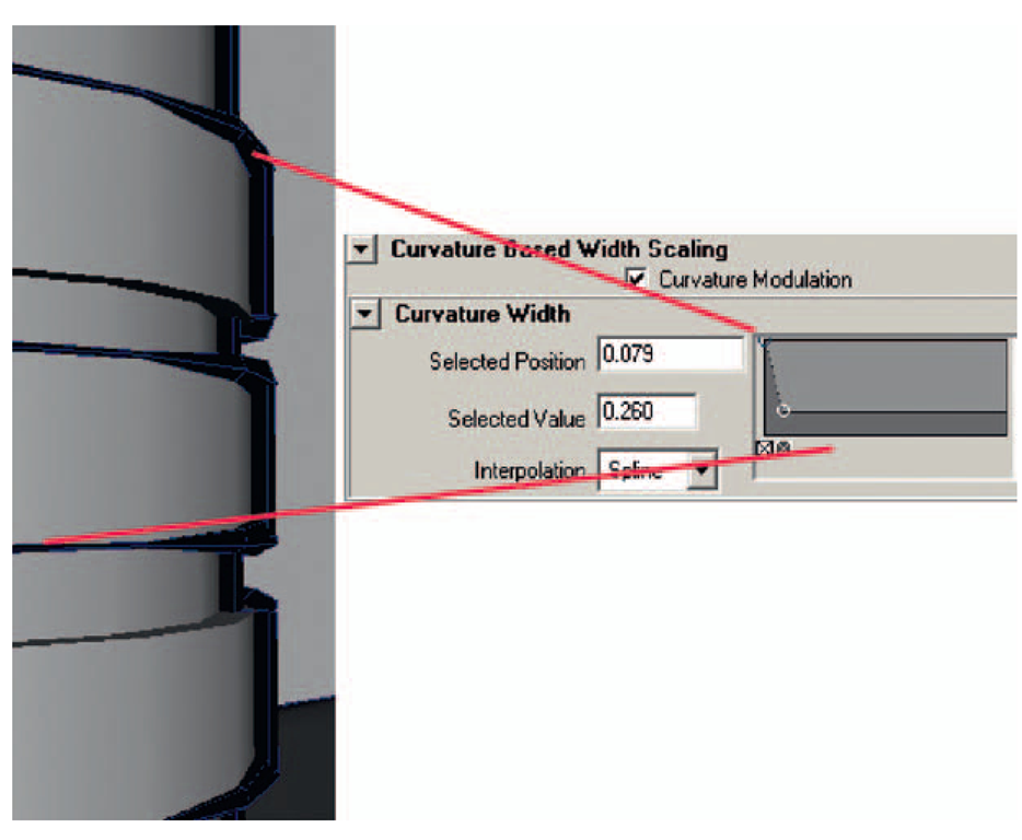
It takes some tweaking. If you get your curve to look like the one shown in Figure 3.20, you can get a little thick and thin depending on how curved the object is, and the straight lines are not as thick as the thin ones:
1. In the profile tab, bring the Profile Width Modulation to .3 to overall adjust the taper.
2. Adjust the Profile Width as necessary to get a line thickness that you like.
3. Test Render.
Creases
The crease in the front of the robot’s chest may not have a toon line. Or perhaps there are other areas where you want to add a toon line. Let’s see how to fix that problem:
FIGURE 3.20 Snapshot of the robot’s neck and the curvature width ramp.
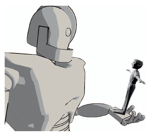
FIGURE 3.21 Robby with the Toon Line and Fill Shader.
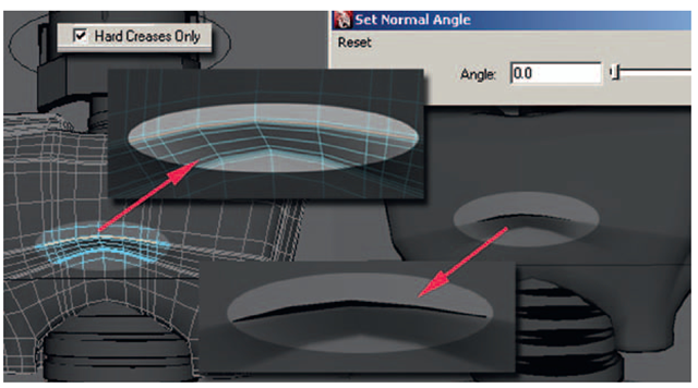
1. Your first instinct might be to go to the crease menu, turn off Hard creases, and adjust the Crease Angle Min to see if you can dial in that specific crease in the robot. However, you end up getting a lot more creases that way, more than you want. (Keep bringing that slider down and you can do a nice wire frame render.)
2. Instead, keep the option for Hard Creases on. Go to edge selection mode and select a line of edges across the crease in the bottom of the rib cage (Figure 3.22).
3. In the Polygon area, select Normals > Set Normal Angle.
4. In the popup window, bring the value to 0 and click OK.
5. Adjust the Crease Width as necessary.
Figure 3.22 shows the visible crease at the bottom of the chest.
Using hard edges only allows you a little more control of exactly what creases are shown.
FIGURE 3.22 The Hard Crease Lines option is turned on and edges in the chest are given hard normals, resulting in a crease line.
