Transformation: Vehicle to Navigation Frame
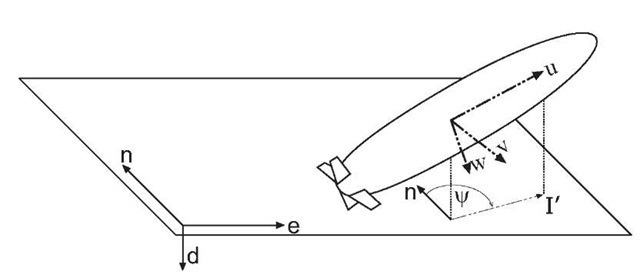
Consider the situation shown in Figure 2.13, which depicts two coordinate systems. The first coordinate system, denoted by (n, e, d), is the geographic frame. The second coordinate system, denoted by (u,v,w) is the vehicle body frame which is at an arbitrary orientation relative to the geographic frame2.
The relationship between vectors in the body and geographic reference frames can be completely described by the rotation matrix![]() This rotation matrix can be defined by a series of three plane rotations involving the
This rotation matrix can be defined by a series of three plane rotations involving the![]() where
where![]() represents roll,
represents roll,![]() represents pitch, and
represents pitch, and ![]() represents yaw angle4.
represents yaw angle4.
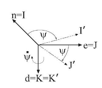
In Figures 2.14-2.16, the axes of the geographic frame are indicated by the I, J, and K unit vectors.
The first rotation, as shown in Figure 2.14, rotates the geographic coordinate system by ^ radians about the geographic frame d-axis (i.e., K unit vector). This rotation aligns the new I’-axis with the projection of the vehicle u-axis onto the tangent plane to the ellipsoid. The plane rotation for this operation is described as 
where
The resultant I’ and J’-axes still lie in the north-east tangent plane.
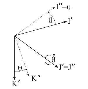
The second rotation, as shown in Figure 2.15, rotates the coordinate system that resulted from the previous yaw rotation by 0 radians about the
Figure 2.13: Relation between vehicle and navigation frame coordinate systems. For navigation in the geographic frame, the origin of the ned coordinate axes would be at the projection of the vehicle frame origin onto the ellipsoid. For navigation in a local tangent frame, the origin of the ned coordinate axes would be at some convenient point near the area of operation.
Figure 2.14: Result of yaw rotation. The initial I, J, K unit vectors align with the tangent frame (n,e,d) directions.
Figure 2.15: Result of pitch rotation. The resultant I" unit vector aligns with the vehicle u-axis.
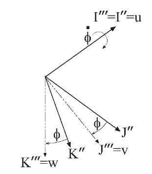
Figure 2.16: Result of roll rotation. The final![]() unit vectors align with the vehicle u,v,w directions.
unit vectors align with the vehicle u,v,w directions.
![]() This rotation aligns the new
This rotation aligns the new![]() with the vehicle u-axis. The plane rotation for this operation is described as
with the vehicle u-axis. The plane rotation for this operation is described as
The third rotation, as shown in Figure 2.16, rotates the coordinate systemthat resulted from the previous pitch rotation by $ radians about the![]() This rotation aligns the new
This rotation aligns the new![]() with the vehicle v and w axes, respectively. The plane rotation for this operation is described as
with the vehicle v and w axes, respectively. The plane rotation for this operation is described as
where
Therefore, vectors represented in geographic frame (or in the local tangent plane) can be transformed into a vehicle frame representation by the series of three rotations:![]()
where the notation![]() The inverse vector trans formation is
The inverse vector trans formation is
Example 2.5 The velocity of a vehicle in the body frame is measured to be
![]() The attitude of the vehicle is
The attitude of the vehicle is![]() What is the instantaneous rate of change of the vehicle position in the local (geographic) tangent plane reference frame? In this case,
What is the instantaneous rate of change of the vehicle position in the local (geographic) tangent plane reference frame? In this case,
Therefore, the vehicle velocity relative to the tangent plane reference system is
Once a sequence of rotations (in this case zyx) is specified, the rotation angle sequence to represent a given relative rotational orientation is unique except at points of singularity. Note for example that for the zyx sequence of rotations, the rotational sequence![]() yields the same orientation for any
yields the same orientation for any![]() Thisdemonstrates that the zyx sequence of rotations is singular points at
Thisdemonstrates that the zyx sequence of rotations is singular points at![]() These are the only points of singularity of the zyx sequence of rotations.
These are the only points of singularity of the zyx sequence of rotations.
The above zyx rotation sequence is not the only possibility. Other rotation sequences are in use due to the fact that the singularities will occur at different locations. The zyx sequence is used predominantly in this topic. In land or sea surface-vehicle applications the singular point (hopefully) does not occur. In other applications, alternative Euler angle sequences may be used. Also, singularity free parameterizations, such as the quaternion, offer attractive alternatives.
When the matrix Rg is known, the Euler angles can be determined, for control or planning purposes, by the following equations
where atan2(y, x) is a four quadrant inverse tangent function and the numbers in square brackets refer to a specific element of the matrix. For example,![]() is the element in the i-th row and j-th column of matrix A.
is the element in the i-th row and j-th column of matrix A.
This section has alluded to the fact that the rotation matrices![]() would have the same form. This should not be interpreted as meaning that the matrices or the Euler angles are the same. The Euler angles relative to a fixed tangent plane will be distinct from the Euler angles defined relative to the geographic frame. Also, the angular rates
would have the same form. This should not be interpreted as meaning that the matrices or the Euler angles are the same. The Euler angles relative to a fixed tangent plane will be distinct from the Euler angles defined relative to the geographic frame. Also, the angular rates![]() are distinct.
are distinct.
We have that
The vector![]() while
while![]() can be non-zero as discussed in Example 2.6.
can be non-zero as discussed in Example 2.6.
Transformation: Orthogonal Small Angle
Subsequent discussions will frequently consider small angle transformations. A small angle transformations, is the transformation between two coordinate systems differing infinitesimally in relative orientation. For example, in discussing the time derivative of a direction cosine matrix, it will be convenient to consider the small angle transformation between the direction cosine matrices valid at two infinitesimally different instants of time. Also, in analyzing INS error dynamics it will be necessary to consider transformations between physical and computed frames-of-reference, where the error (at least initially) is small. In contrast, Euler angles define finite angle rotational transformations.
Consider coordinate systems a and b where frame b is obtained from frame a by the infinitesimal rotations![]() about the third axis of the a frame,
about the third axis of the a frame,![]() about the second axis of the resultant frame of the first rotation, and
about the second axis of the resultant frame of the first rotation, and![]() about the first axis of the resultant frame of the second rotation. Denote this infinitesimal rotation by
about the first axis of the resultant frame of the second rotation. Denote this infinitesimal rotation by![]() The vector transformation from frame a to frame b is defined by the series of three rotations:
The vector transformation from frame a to frame b is defined by the series of three rotations:![]() Due to the fact that each angle is in finitesimal (which implies that
Due to the fact that each angle is in finitesimal (which implies that![]() for
for![]() the order in which the rotations occur will not be important. The matrix representation of the vector transformation is
the order in which the rotations occur will not be important. The matrix representation of the vector transformation is
where![]() is the skew symmetric representation of
is the skew symmetric representation of![]() as defined in eqn. (B.15). To first order, the inverse rotation is
as defined in eqn. (B.15). To first order, the inverse rotation is


![tmp20-424_thumb[2] tmp20-424_thumb[2]](http://what-when-how.com/wp-content/uploads/2012/02/tmp20424_thumb2_thumb.jpg)
![tmp20-431_thumb[2] tmp20-431_thumb[2]](http://what-when-how.com/wp-content/uploads/2012/02/tmp20431_thumb2_thumb.png)
![tmp20-432_thumb[2] tmp20-432_thumb[2]](http://what-when-how.com/wp-content/uploads/2012/02/tmp20432_thumb2_thumb.png)
![tmp20-435_thumb[2] tmp20-435_thumb[2]](http://what-when-how.com/wp-content/uploads/2012/02/tmp20435_thumb2_thumb.png)
![tmp20-439_thumb[2] tmp20-439_thumb[2]](http://what-when-how.com/wp-content/uploads/2012/02/tmp20439_thumb2_thumb.png)
![tmp20-444_thumb[2] tmp20-444_thumb[2]](http://what-when-how.com/wp-content/uploads/2012/02/tmp20444_thumb2_thumb.png)
![tmp20-452_thumb[2] tmp20-452_thumb[2]](http://what-when-how.com/wp-content/uploads/2012/02/tmp20452_thumb2_thumb.png)
![tmp20-459_thumb[2] tmp20-459_thumb[2]](http://what-when-how.com/wp-content/uploads/2012/02/tmp20459_thumb2_thumb.png)
![tmp20-478_thumb[2] tmp20-478_thumb[2]](http://what-when-how.com/wp-content/uploads/2012/02/tmp20478_thumb2_thumb.png)
![tmp20-483_thumb[2] tmp20-483_thumb[2]](http://what-when-how.com/wp-content/uploads/2012/02/tmp20483_thumb2_thumb.png)
