Abstract
The objective of this research is to define drill speeds that produce acceptable results when using the hole-drilling technique for measuring residual stress. For this study, three common engineering materials; alloy 6061-T651 aluminum, 304 stainless steel, and A36 carbon steel were used. This was achieved by performing ESPI/hole-drilling stress measurement of a known applied stress in discrete rpm intervals ranging from 2-40K rpm for each material. To produce a known state of stress specimens were bent elastically in a four-point bend fixture. Stress measurements were taken using single-axis electronic speckle-pattern interferometry (ESPI). It was found that for 6061-T6 aluminum, accurate and repeatable results can be achieved between speeds of 2-40K rpm. For 304 stainless steel, result accuracy diminishes when drill speeds go below 6K rpm. The A36 steel had a large as-received stress gradient across the longitudinal dimension and was therefore removed from this study.
Introduction
Residual Stress (RS) is locked in stress that is induced due to non-uniform treatment of materials and exists in the absence of applied loads. RS is usually unwanted, unavoidable, and will promote premature failure of a part or assembly. RS is often purposely induced into a part or material, and is called "engineered stress". Shot and laser-peening, for instance, introduce compressive residual stresses to a surface layer of a part, significantly increasing its fatigue life [1]. Residual-stresses arising from metal forming and machining and the grounds for their induction have challenged the minds of engineers and scientists since the Industrial Revolution. Figure 1 shows a classic photograph of the spontaneity of residual stress effects, which highlights the significance of its presence.
Fig. 1 Beam split from relaxation of residual stresses [2]
When the science of residual-stress progressed to the point to where its actual measurement could be employed (1930s), an explosion of thought resulted in ways to increase accuracy and improve results. Fueled with the desire to more accurately reveal these undesired stresses, theories have been proposed and experiments performed.
The conclusion of a study conducted in the 1980s inferred that for hole-drilling residual-stress measurement, one should use the highest drill-speed attainable in order to minimize induced drilling stresses and ensure accurate data [3]. Since then, it has just been standard to use the highest speed attainable. Flaman’s study of the effect of drill-speed on the accuracy of hole-drilling residual stress measurements is the only of its kind contained in the literature.
The aim of the current study is to obtain more data, which will give a better picture of what effects are taking place when varying drill-speeds are utilized. The previous study was conducted using an air-turbine spindle along with strain-gage rosettes, whereas, this study will use a state-of-the-art NSK electric spindle and controller combined with a laser speckle interferometer. Air turbines have variable speed as a function of load which very likely decreases by a significant amount under load. Therefore, air turbines are not particularly appropriate for studying drill-speed effects, which is why the electric drill and feedback controller have been employed. Additionally, using an ESPI system for strain measurement, rather than strain-gage rosettes, will enable the acquisition of many residual-stress measurements in a short period of time. While it has been shown that holes drilled at low speeds (~2K rpm) will produce larger strain readings than holes drilled at ultra-high speeds ~400K rpm, there is a huge data gap between these two extreme values. Taking many measurements between 2K and 40K rpm and using the data to find out where result accuracy actually begins to diminish is the primary purpose of this study. Any information gained with the ESPI system can be applied back to the hole-drilling/strain-gage technique.
Material Procurement
The .5" plate materials used in this study were all rolled plate stock and comprised of, 6061-T651 aluminum, A36 carbon-steel, and 304 stainless-steel. All materials were purchased from Reliance Steel & Aluminum Company in Albuquerque, NM.
Sample Preparation
Bar specimens, of dimensions 12"x1"x0.5" (304.8 x25.4 x12.7mm3), were very carefully machined from each of their 16"x16"x0.5" (406.4 x406.4 x12.7mm3) parent plates as to minimize induced machining stresses. The specimen plates were specified to be cut away from the edges of the parent plates in order to avoid the stress gradients close to the edges of large rolled plate [8]. The material properties were acquired from each material’s certified test report. Each bar specimen was slow cut on a band saw with cutting lubrication/cooling fluid and then side-milled with a carbide tip, under flood coolant, to a final dimension of 12"x1"x.5". The specimens’ longitudinal dimension runs parallel to the rolling direction. All machining processes were performed by Hand Precision Machining, Inc., of Los Alamos, NM.
Experimental Apparatus
ESPI/Hole-drilling Equipment
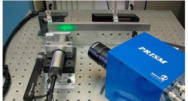
An electric high-speed machining spindle with a range of 2K-40K rpm and electronic feedback controller were used in conjunction with an American Stress Technologies, PRISM system [4,5,6,7]. The function of the ESPI system is based on the hole-drilling method of residual-stress measurement but uses holographic techniques, rather than strain gages, to measure strain due to stress relaxation. The laser is of wavelength 532nm and power 20mW. However, the laser is mounted, in this particular experiment, to 7.5mW and the beam is expanded to a 32mm diameter. This setup was chosen to reduce the laser intensity to adhere to workplace safety protocol. The ESPI/hole-drilling system is used to drill a hole into a surface which is illuminated by a speckle pattern. When the hole is drilled, if residual stress is present, deformation around the hole occurs, which changes the intensity of light at and around the hole. The change in intensity is found by subtracting before and after images of the speckle pattern. This intensity change is converted into the corresponding deformation along the sensitivity angle. The sensitivity angle is the bisector of the illumination and observation vectors. From the deformation, the stress state in the in-plane dimension is found.
The ESPI system is capable of using drill-bits of sizes ranging from 1/32" to 1/8" (0.79375 to 3.175mm). This range relies on the camera’s ability to properly image the drilled hole. Proper adjustment of the camera is performed prior to drilling so that the hole diameter will comprise 1/8 to 1/4 of the on-screen image.
The choice of hole-depth is dependent on the chosen diameter of the hole. The depth to diameter ratio, ‘D/d’, usually does not exceed 0.6. There is a depth at which further drilling will not produce any response at the surface. The numerical models used with the ESPI system allow D/d ratios ranging from 0.1 to 0.6. Table 1 lists the most common depth-bit configurations.
Table 1 Depth to diameter, D/d, ratios for common bits
|
Depth/diameter ratio |
0.1 |
0.2 |
0.3 |
0.4 |
0.5 |
0.6 |
|
Bit size |
- |
- |
- |
- |
- |
- |
|
1/64 – 0.0156" |
0.0016" |
0.0031" |
0.0047" |
0.0063" |
0.0078" |
0.0094" |
|
(0.397) |
(0.040) |
(0.079) |
(0.119) |
(0.159) |
(0.198) |
(0.238) |
|
1/32 – 0.03125" |
0.0031" |
0.0063" |
0.0094" |
0.0125" |
0.0156" |
0.0188" |
|
(0.79) |
(0.079) |
(0.159) |
(0.238) |
(0.318) |
(0.397) |
(0.476) |
|
3/64 – 0.0469" |
0.0047" |
0.0094" |
0.0140" |
0.0188" |
0.023" |
0.0281" |
|
(1.19) |
(0. 119) |
(0. 238) |
(0. 357) |
(0.476) |
(0.595) |
(0.714) |
|
1/16 – 0.0625" |
0.00625" |
0.0125" |
0.0188" |
0.0250" |
0.03125" |
0.0375" |
|
(1.59) |
(0.159) |
(0.318) |
(0.476) |
(0.635) |
(0.794) |
(0.953) |
|
3/32 – 0.0938" |
0.0094" |
0.0188" |
0.0281" |
0.0375" |
0.0469" |
0.0563 " |
|
(2.38) |
(0.238) |
(0.476) |
(0.714) |
(0.953) |
(1.191) |
(1.429) |
|
1/8 – 0.125" |
0.0125" |
0.025" |
0.0375" |
0.050" |
0.0625" |
0.0750 " |
|
(3.18) |
(0.318) |
(0.635) |
(0.953) |
(1.27) |
(1.588) |
(1.905) |
Four-point Bend Fixture
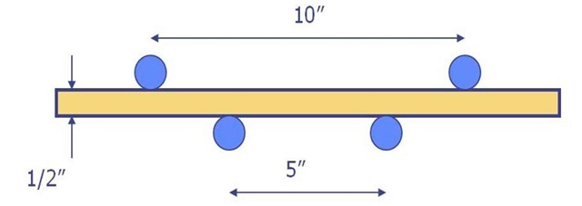
In an effort to fulfill the need for a standard method of creating a sample with a non-uniform through-thickness stress distribution, a load fixture was developed [9]. This fixture was designed to help assess the accuracy of residual-stress measurement methods and is therefore used in this study. A schematic of the load fixture pin locations are displayed below in Fig. 2.
Fig. 2 Schematic of 4-point bend fixture, pin locations
The pins are designed to rotate during the bend process eliminating traction forces. Through integration of the moment equation for the fixture, one can find the centerline deflection to be expressed as:
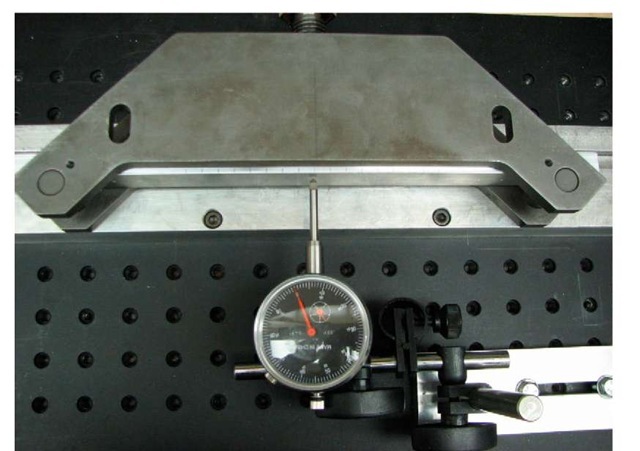
Where l is the distance between the outer supports (10"), a is the distance between the inner supports (2.5", 63.5mm), t is the thickness of the specimen (0.5", 12.7mm for specimens used in this study), G is the desired surface stress between the inner supports, and E is the modulus of elasticity (Table 2). This equation is used to give a deflection value at which the desired stress is achieved in the surface of the beam. The centerline deflection of the specimen is measured using a dial-gage scaled in increments of .001" (Fig. 3).
Table 2 Material properties of 6061-T651 aluminum and 304 stainless steel
|
Material |
Elastic Modulus |
Poisson’s Ratio |
Yield Stress |
|
6061-T651 Aluminum |
10,300ksi (71.1 GPa) |
0.344 |
41.8ksi (288 MPa) |
|
304 Stainless Steel |
27,600ksi (190.4 GPa) |
0.305 |
39.6ksi (273 MPa) |
Fig. 3 Measurement of specimen centerline deflection with dial gage
Experimental Procedure Quantifying As-Received State of Stress
Before any worthwhile experimental comparison on a series of materials can be performed, the initial conditions of each test specimen should be evaluated. For this particular test, in which we seek to compare stresses, the presence, location and orientation of the existing stresses should be determined. For clarity, the longitudinal axis is along the 12" dimension and the transverse along the 1". All holes were drilled in the 12" x1" face of each specimen. In order to characterize the as-received state of stress, a row of four .0625" (1.59mm) diameter holes was drilled at a depth of .0125" (.318mm), on the face of each specimen along the longitudinal axis. The four holes were located at 2" and 2.5" from each end. Drill-bits were changed every 15 holes in the aluminum and every 8 holes in both steels for the as-received measurements. Using machinist clamps and an aluminum block, the bar specimen were secured for drilling (Fig. 4).
Fig. 4 Specimen fixture for as-received stress measurements
Parameter Variation
For all tests, two-flute carbide tipped end mills were used to drill the holes and were changed every 15 holes. Hole-centers were spaced at a distance of five hole-diameters to minimize the measurement results at one location being affected by the stress relief from a previously drilled hole. Each row was positioned .25" from the top and bottom edge of the specimens in order to minimize edge effects and still maintain enough distance in between the hole-centers in opposing rows. A .0625" (1.59mm) diameter drill-bit was used which gives, since two rows of measurements were taken and each hole center should be spaced at least 5 hole-diameters, 30 potential measurements on each bar specimen (Fig. 5). The parameters varied in this study are drill-speed, hole-depth/diameter ratio, and drill-bit size.
Drill-speed
After characterization of the as received surface stress, the aluminum and stainless steel specimens were elastically deformed in a four-point bending fixture to create a known surface stress equating to ~50% of the yield stress for each material ; 20 ksi (138 MPa) and 15.6 ksi (107.6 MPa) at the surface for 6061-T6 aluminum and 304 stainless steel respectively. These values were chosen in order to adhere to the 50% of yield-stress limit rule for hole-drilling/strain gage residual stress measurement accuracy [10]. It has been shown that errors in residual stress results are obtained when measuring stresses that are greater than 50% of the yield stress of the material [11]. This overestimate is caused by localized plasticity effects occurring at the periphery of the hole due to the stress concentration factor of the hole. The highest stress obtainable without inducing plasticity effects was desired so the measurement’s error and uncertainty would have less weight on the overall accuracy of our measurements.
A total of thirty, .0625" diameter, holes were drilled in both, 6061-T6 aluminum specimen 1 (Al-1) and 304 stainless steel specimen 1 (SS-1) at a depth of .0125" (0.318mm). Holes 1 through 15 in these specimens were drilled at 40K rpm, 16-18 at 12K rpm, 19-21 at 10K rpm, 22-24 at 8K rpm, 25 and 26 at 6K rpm, 27 and 28 at 4K rpm, and 29 and 30 at 2K rpm. This gives a total of seven drill-speed increments for each specimen.
Fig. 5 Aluminum (top) and annealed stainless-steel (bottom)
In 6061-T6 aluminum specimen 2 (Al-2), five .0125" depth holes were drilled per drill-speed-increment in a series of thirty holes. This gives six speed increments, in descending order, at 40K, 30K, 20K, 14K, 8K, and 2K rpm.
The speed increments for stainless steel specimen 2 (SS-2) were chosen to be, in descending order, 40K, 20K, 10K, 8K, 6K, and 4K rpm.
Depth
While maintaining a speed of 40K rpm, the hole-depth/diameter ratio was varied from 0.2 to 0.6 to investigate any effect on measurement accuracy. Fifteen .0625" (0.318mm) diameter holes were drilled in both specimens Al-3 and SS-6. The fifteen-hole series began at one end of the bar and finished at the other. Holes 1 through 5 were produced at a depth of .0125" (.318mm) (D/d = 0.2), 6-10 at .0250" (.635mm) (D/d = 0.4), and 11-15 at .0375" (.953mm) (D/d = 0.6). The procedure utilized for stainless steel specimen 6 (SS-6) was identical.
Bit-diameter
The final parameter variation investigated is that of drill-bit diameter. The drill-speed and D/d ratio were held constant at 40K rpm and 0.2 respectively. Specimens Al-3 and SS-6, also used for depth variation, will be flipped end on end and then used for the bit-variation tests. The first 5 holes from the depth variation test in each material (40K rpm, .0625" diameter, and .0125" depth) were used as a baseline comparison for the data from the other two bit sizes.
In aluminum specimen 3(Al-3), four holes (16-19) were drilled with a .03125" (0.79mm) diameter bit, at a depth of .0063" (0.159mm). Next, four holes (24-27) were drilled with a .125" (3.18mm) diameter bit at a depth of .025" (0.635mm).
In stainless steel specimen 6 (SS-6), eight holes (16-23) were drilled with a .03125" (0.79mm) diameter bit at depths of .0063" (0.159mm). Then, five holes (24-28) were drilled with a .125" (3.18mm) diameter bit at depths of .025" (0.635mm).
![Beam split from relaxation of residual stresses [2] Beam split from relaxation of residual stresses [2]](http://what-when-how.com/wp-content/uploads/2011/07/tmpA144_thumb_thumb.jpg)


