Abstract
Most owners and managers of commercial and industrial facilities recognize the value of using interval energy information to allocate costs to building users and fine-tune building operations, but find that installation costs are very high in existing buildings. Some of the most promising technological developments in the submetering world are centered on the use of wireless devices to gather data from the meters, communicate it to a central data acquisition location, and forward the interval data to a remote server using wireless Web networks. This entry examines some of the key elements of wireless energy information and control networks and provides an overview of important underlying wireless infrastructures. Particular emphasis is placed on using “mesh” radio networks to communicate raw meter data within a building or campus and using GSM/general packet radio service (GPRS) cellular networks for long-haul communications.
INTRODUCTION
Recent volatility in energy prices has made submetering (i.e., any meter located on the customer side of the primary utility meter) a valuable tool for building operations and management. One of the biggest obstacles to getting this kind of information has been the high cost of running wiring from the meter hardware (gas, electricity, water, etc.) to a data acquisition device in existing buildings. Many radio manufacturers (such as Maxstream and AeroComm) have introduced low-cost radio modules that can be adapted to provide the backbone of a wireless metering system. Using these off-the-shelf radio modules in conjunction with specially designed hardware and software for RS485 communications provides a seamless wireless communications network for both new and existing meters. In addition to this internal communications network, the development of GSM/general packet radio service (GPRS) cellular networks for wireless networking (think personal digital assistants (PDAs) with email capability) provides a convenient means of gathering interval data from locations around the world without the need for connecting to an existing local area network (LAN) or phone line.
A SUBMETERING PRIMER
For most end users, when we use the term “submetering,” the immediate image is of the hardware installed on the electrical system to measure kW and kWh. While these devices are certainly an indispensable part of a submetering system, they are only one of the components. A successful submetering system takes the raw data from one or more meters and converts it into useful and timely information to be used for the following:
• Cost allocation to tenants
• Operational analysis and improvement
• Measurement and verification of energy savings
• Benchmarking and accountability
Converting the raw data at the meter level to actionable information requires several steps. Within the metering industry, this process can best be illustrated by looking at five key components:
1. Meters and sensors—This is the hardware level where the devices are actually installed in the electrical (or gas or water) system to capture energy consumption for one or more different areas of the building. In the electrical system, these meters might be the traditional round glass meters or they might be meters designed especially for submetering.
2. Internal communications—This is the mechanism used to communicate data from the meters and sensors to the data acquisition server (DAS). In traditional applications, this is usually a simple twisted pair of wires connected on an RS485 serial daisy chain.
3. Data acquisition—The meters and sensors from level 1 produce industry standard outputs (e.g., pulse or Modbus) that correspond to the real-time outputs being monitored. For example, each pulse from an electrical or flow meter has an assigned value (e.g., 1 pulse = 10 kWh). In order for this raw data to be utilized, it must be captured in a timely manner, time-stamped, and made available for presentation.
The DAS takes this raw data, time-stamps it, and then sends it to a local or remote server for storage and report generation.
4. External communications—Once the data is collected by the DAS, it is sent to a local or remote server for reporting. In traditional metering applications, this communication may use a LAN connection or a modem.
5. Storage and reports—Once the data from the meters is gathered at the building level, it still requires further processing to produce user-friendly reports and information. This processing occurs at the user interface level, where information from one or more buildings is collected into a traditional database for reporting and storage.
A detailed discussion of each of these components is beyond the scope of this entry, but most successful submetering systems have the following characteristics:
• “Open” meter protocols that provide the capability for any DAS to connect to any meter or sensor, regardless of what is being measured (e.g., electricity, gas, water, flow, british thermal units (BTUs)). Most meter manufacturers use Modbus remote thermal unit (RTU) as the primary protocol for communications with submeters, but the DAS should also accept pulse or analog values that meet industry standards.
• Nonvolatile storage of data—the DAS should be able to store at least 30 days of data from multiple meters without the risk of data loss in the event of power failure.
• Options for user-selected data intervals—the user should be able to select data intervals to match the utility interval (e.g., 15 min).
• “Open” protocol support at the DAS level that allows the data collected to be sent to any Web server (i.e., nonproprietary format). In most cases, this can be accomplished using standard Internet protocols such as HTTP, FTP, and XML. This allows the end user to select virtually any software program (including custom programs), regardless of the DAS or meter brand.
Fig. 1 (below) shows a graphical representation of a traditional wired submetering system, starting with the meters and sensors at the bottom and moving up to the storage and reports level at the top of the figure.
WHY DO WE NEED WIRELESS SUBMETERING?
As outlined in the previous section, there are readily available wired solutions that provide reliable submetering data using commonly available tools such as serial ports and LANs—so why do we need wireless? The simplest answer is that in many applications (particularly retrofits), the cost of running wire between meters and the DAS is prohibitively expensive, and using wireless components can dramatically reduce both the cost and the installation time. In addition, in many submetering projects, the cost and time involved in securing a network connection or phone line for communicating from the DAS to the Internet becomes a major headache.
Using wireless solutions in submetering not only minimizes the costs of many projects, but it also greatly reduces the disruption of day-to-day operations caused by running wire several hundred feet or more through an existing facility. Wireless also provides a very attractive alternative to trenching between buildings in a campus environment and eliminates the need for coordinating with the IT department for use of an existing LAN connection.
WHICH “WIRELESS” ARE WE TALKING ABOUT?
Ask anyone what the term “wireless” means, and you’ll probably find yourself on the receiving end of one of those looks that implies you must be one of the dumbest people on Earth. Wireless, as any fool knows, means no wires, and therein lies the problem with understanding wireless submetering. A short list of wireless terms includes the following:
• Satellite
• Cell phone
• Wi-fi
• Pager
• Proprietary radio
• Bluetooth
• Zigbee
In essence, wireless (or for that matter, wired) communications form the bridge between each of the levels of metering discussed above. We will be examining two different wireless applications in this entry, the first being communications between meters and the DAS and the second the communications of interval data from the DAS to a remote server for storage and reporting.
PART I-METER-LEVEL WIRELESS COMMUNICATIONS
One of the most expensive aspects of adding submetering to an existing facility or facilities is the cost of running wires from multiple locations to the central data acquisition point. This cost can be significant, particularly when wiring must be run between multiple buildings (i.e., campuses or bases). The first level of wireless communications we will consider is the communication of data from meters and sensors wirelessly to the DAS. This level represents the area in which technology is advancing the most rapidly, as electronics developed for a wide variety of wireless communications are being utilized to reduce the cost of submetering.
A BRIEF PRIMER ON WIRELESS TERMS
A detailed technical discussion of wireless technologies is beyond the scope of this entry, so the purpose here is just to provide a brief overview that will serve as a jumping-off point for later discussion. At the most basic level, all wireless communications are based around radio waves, not unlike the over-the-air broadcast of radio and TV signals. (For the younger readers, yes; it is true that in the olden days, TV was limited to a half-dozen channels captured out of the air with a pair of rabbit ears.) There are significant differences between the radios used, but at the heart are some shared attributes that help to determine the suitability for use in wireless metering. Among the most common and important terms associated with radios are the following:
1. Frequency—Frequency refers to the time between peaks of the radio signal generated by the radio. In order for two radios to communicate with each other, they must be tuned to the same frequency, whether in a broadcast (one-way) or two-way communication environment.
2. Power—Most radios are rated for specific power levels that serve to determine how far a signal can be detected.
3. Interference—As anyone who has ever driven under a power line or tried to use a cell phone knows, there are a number of things that can cause interference with a radio signal, and the same is true for wireless metering technologies. Concrete walls, steel panels and other radio sources all provide challenges to the successful communication of metering data.
4. Throughput—A combination of the above factors, plus a few others, determines the throughput of the radio system. Basically, this just means how much data can be successfully transmitted in a given period of time, including any repeat requests or other delays.
5. Repeaters—Despite the best design of radios, it is very likely that there may be “dead spots” or areas where radio transmission is not successful. This may be due to interference, lack of power, or some other factor; but regardless of the cause, it may be necessary to install repeaters, which are basically designed to relay a lost or weak signal from one point to another.
6. Mesh networks—The term “mesh network” refers to networks designed to be self-healing radio networks that automatically configure themselves to optimally send data to one or more other radios without the need for setup and configuration by the user.
7. Magic—One of the most interesting characteristics of most radio networks is that they represent a blend of science and art. Most cell phone users have experienced the joy of having a cell phone that always works in a particular location, but suddenly doesn’t, and the same magic applies to radios used for metering applications. While there are many tools available to assist in predicting the odds of success in any given location, the reality of wireless communications is that even the best of tools may not prove 100% reliable.
WIRELESS SERIAL COMMUNICATIONS NETWORKS
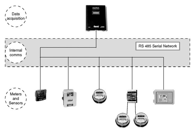
In order to better understand some of the options available for wireless communications between meters and the DAS, let us take a closer look at the wired version of this same communication. Fig. 2 shows a section of the previous figure that focuses on the internal serial communications networks for submeters.
As Fig. 2 shows, in a wired sensor-level communications network, a twisted pair of wires is run from a serial port (RS485) on the DAS and daisy chained to each of the Modbus meters or devices. The DAS uses plug-and-play technology to detect the type of meter and load the appropriate drivers to interrogate the meter(s) to obtain the desired data. On preselected intervals (typically 15 min or 1 h), the DAS will gather data from the meters that may be limited to consumption (kWh) or may include other parameters such as power factor or total harmonic distortion (THD), if the meter supports those additional functions. The readings are then stored by the DAS until they are “pushed” or “pulled” to a remote server for storage in a standard database (more on that later).
This system is quite reliable and provides an excellent method of communication if the meters and the DAS are all in close proximity. This type of serial network is typically capable of reliable communications up to 4000 ft. On the other hand, if there are multiple locations throughout the facility or campus that make wiring difficult or expensive, wireless nodes near the meters can provide a very cost-effective alternative to wiring.
HOW DOES WIRELESS SERIAL COMMUNICATION WORK?
There are at least a couple of different ways of wirelessly transferring data from meters. One method involves using low-powered battery devices to capture and transmit pulses from meters to the DAS, which represents a very low-cost means of communications, but is not a replacement for the ideal serial network shown above. The wireless nodes function in one-way communication only and cannot provide the reliability or the additional data available from reading and sending Modbus serial data to the network.
Fig. 2 Internal metering components view.
The second (and preferred) method is to simply use wireless nodes on either end of the transmission to seamlessly replace the twisted pair of wires in Fig. 2. The newest technologies on the market accomplish this in a mode that is completely transparent to the user (i.e., the data transmitted wirelessly is indistinguishable from the data gathered on a wired network).
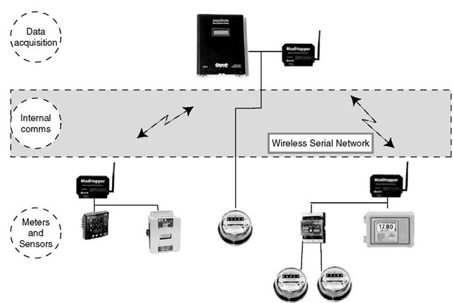
Fig. 3 shows a typical system that substitutes wireless Modbus communications for wired networks. In this case, we will assume that the two meters on the left of the graphic are located in one electrical room; the three on the right are located in a second electrical room; and the single meter in the center is the primary meter for the facility, which is located in close proximity to the DAS, and thus can be hard-wired.
In this example, all of the meters can communicate all of their data using the standard Modbus protocol, regardless of whether they are connected wirelessly or via wires. In the case of the remote meters, we have simply wired the RS485 outputs from the meters into a wireless node that puts the Modbus data into a wireless form and sends the data via radio to another node connected directly to the DAS, where the data is once again converted to RS485.
SO HOW DOES THIS MESH NETWORK FUNCTION?
The two keys to making the wireless communications network shown in Fig. 3 actually work are (1) that the individual radio transceivers (or nodes) are specifically designed for transmitting Modbus data and (2) that the radios contained within the transceivers can function as part of a “mesh” network. A brief overview of the functioning of a mesh network will provide a better understanding of the benefits of using wireless mesh networks to replace wired serial communications.
All mesh networks (regardless of the application) share certain common characteristics that make them valuable for replacing or augmenting wired networks. Among the most important are:
• Self-configuring nodes—The whole concept of mesh networks is that the radio nodes will be aware of other nodes and will automatically configure the network to optimize throughput of data, without the need of programming or configuration on the site.
• Multiple routing paths—Because each node is “aware” of all the other nodes it can communicate with, there are multiple options available for routing the data. As new nodes are added to the network, the network should recalculate the optimal routing paths to take advantage of more efficient routing options.
• Spread spectrum radios—This feature allows the radios to work on a variety of predetermined frequencies, minimizing the likelihood of interference from other radio sources. Essentially, the radios are designed to “hop” to different frequencies if interference is encountered, until the two radios find a frequency that minimizes interference. • ISM band radios—Transceivers that use the instrumentation, scientific, and medical (ISM) frequencies set aside by the FCC do not need to have a local license for each site. These radios are designed to share the frequency bands with other systems and devices with a minimum of interference.
Fig. 3 Metering components with wireless communications.
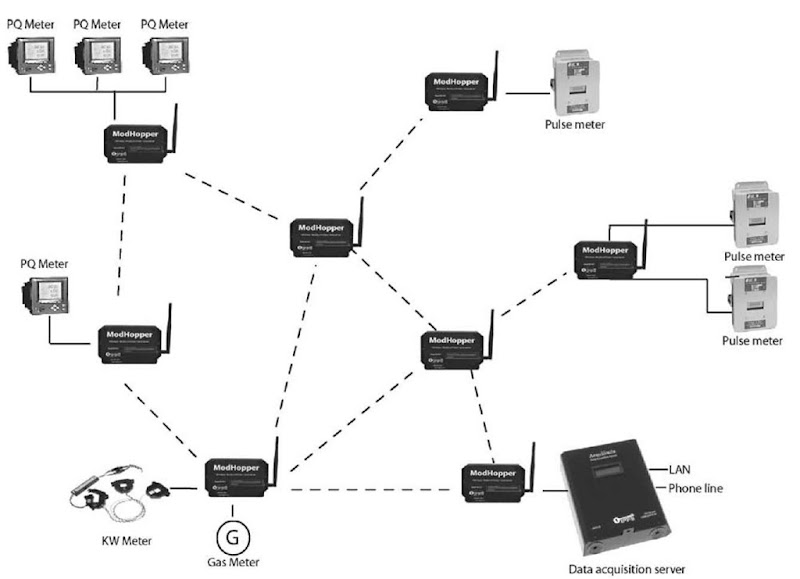
Fig. 4 shows a diagram of a typical wireless mesh network. Each of the transceivers can accept up to 32 Modbus devices and 2 pulses.
This figure shows a mesh network with eight transceivers and nine meters, all connected to a DAS for data collection. Two of the transceivers are functioning as repeaters, because they have no meters connected and serve only to route traffic to other nodes. The dashed lines between the transceivers show the other nodes that each can communicate with, and most of the nodes can see multiple other nodes, providing multiple routing paths for requests for data from the DAS. The network will automatically figure the optimal routing to reach each of the meters and will adjust these routing paths based on the success rate of transmissions. If other Modbus devices are added to any of the nodes, their presence is detected by the network and optimal routing paths are determined. If other transceivers are added, they will similarly be detected by the network and added to the routing paths.
SUMMARY
The technology available today makes wireless submetering a viable alternative to hardwired systems. The installation of these products, whether as the total solution or in conjunction with wired Modbus meters, provides a transparent and cost-effective option when wiring costs are prohibitively expensive.
PART 2—EXTERNAL WIRELESS COMMUNICATIONS
Summary
Just as mesh networking provides an excellent alternative to a wired solution at the sensor communication network level, advances in wireless technology allow the user to send data from the DAS to a remote server without the need for a hardwired connection. The use of GSM/GPRS (cell) modems in the DAS provides a very cost-effective means of communications that piggybacks on the structure built out for cell phone communications.
WIRED EXTERNAL SOLUTIONS
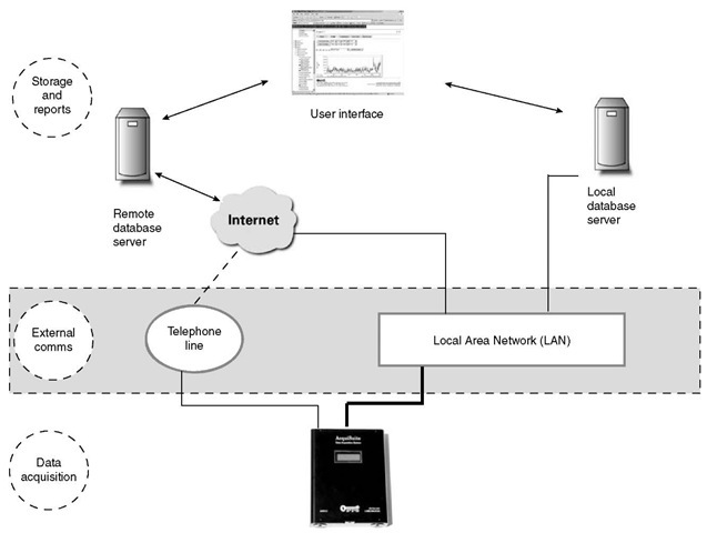
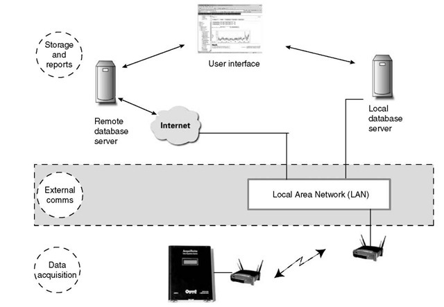
Fig. 5 shows a closer look at the upper part of Fig. 1 and provides some details about how data is typically sent from the DAS to a remote server for logging and reports. The DAS provides several options for communications, depending on the needs of the user and available communications options. There are usually two alternatives for connecting to either a remote or a local server:
Fig. 4 Typical mesh network metering system.
• Existing LAN—If the DAS is located in a facility that has an existing LAN, this provides an excellent mechanism for getting data from the DAS to a server. The DAS is IP-addressable, which means that a network-connected DAS can provide two-way communications and allow the user to see near real-time data in addition to interval information.
• Phone line—If there is no LAN connection (or if the IT department cannot or will not make a connection available), the DAS also provides the option to use an on-board modem to dial in or out to the system. If the user only needs to upload data (dial-out), the phone line can be shared with other devices such as fax machines.
Details of the file upload in a wired system are beyond the scope of this entry, but a typical upload session on an existing LAN would have the following elements:
1. The DAS initiates a connection to the remote server via the LAN by accessing a URL (e.g., http://www.obvius.com) where the server is located. The DAS provides a user name and password to the server, which uses this information to access the existing database records.
2. Once the connection is established and verified, the DAS will upload data collected since the last upload, in most cases using HTTP or FTP protocols.
3. Once the data is uploaded and verified, the DAS can optionally get additional information from the server, such as time checks.
4. Finally, the session is terminated.
The process for using a phone line connection is very similar, with the primary difference being that the upload speeds are slower (think dial-up modem vs DSL) and the connection is a PPP session.
WIRELESS OPTIONS FOR EXTERNAL COMMUNICATIONS
There are two basic applications for wireless communication from the DAS—one for inside the building to a LAN and one for totally wireless communications.
We will first look briefly at the simpler of the two, wireless communications within the building.
In this scenario, we are simply substituting a wireless access point for the wired LAN connection that then connects to another wireless access point on the local LAN. Because the DAS is an IP-addressable device like any workstation, there is no special setup required, and the functionality is exactly the same as that shown for the wired LAN connection in Figs. 5 and 6.
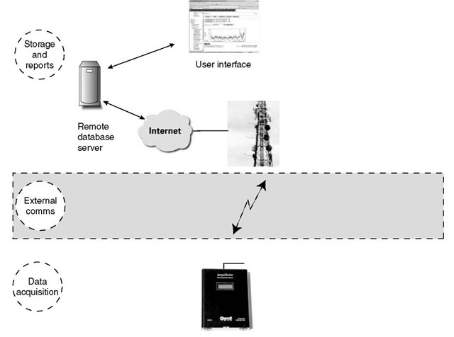
The second option for wireless external connectivity uses the existing cell phone networks built around the country to bypass any local connection. The primary reasons for doing this are the following:
• Lack of available LAN or phone lines
• Security concerns from IT personnel about using existing LANs
• High cost of acquiring and maintaining either phone or LAN connections
• Delays in getting phone or LAN connections installed Ease of installation
WHAT ADDITIONAL HARDWARE IS REQUIRED?
In the simplest terms, the only real change from the LAN to the phone-connected version is that a cell phone modem is used in place of the typical RJ11 modem. This modem is connected to an antenna mounted on the DAS, but these are the only functional differences between the cell modem version and any other DAS.
HOW DOES IT WORK?
In the olden days (think 1990s), cell phone communication was based on taking analog voice signals from one user and transmitting them to an analog receiver held by another user on the other end. Today, analog transmission is virtually nonexistent—ithas been replaced by digital cell technology (basically a process that converts the analog voice signal to digital for transmission that is decoded on the other end). The evolution from analog to digital is beneficial for data communication because data transmission on the Internet is inherently digital, and thus ideally suited for the digital networks (Fig. 7).
Fig. 5 Wired paths to the Web or a local database.
Fig. 6 Wireless Ethernet connection.
Fig. 7 Cell-based Web connection.
The DAS is functionally the same device used in the hardwired (LAN or phone modem) connection shown earlier in this entry. To use the cell phone system for data transmission, the phone modem module is replaced with a cell modem that connects to the cellular network just like any cell phone. The system relies on the use of the GSM network using GPRS to transmit data packets wirelessly over the cell network. This is the same system and service used by cell providers to allow users to view email and browse the internet using cell phones and PDAs.
Implementing this method of communication requires a SIM card (available from the wireless carrier) and a monthly data plan from the same carrier (e.g., Cingular) that typically runs $20-$30 per month for most DAS installations.
WHY USE THE CELL NETWORK INSTEAD OF A LAN OR PHONE LINE?
In addition to the ongoing monthly costs of cell service, the GSM version of the DAS is also typically 20%-30% more expensive than an identical LAN version, and the upload times are much slower. So, the obvious question is: Why anyone would use the cell system? There are a number of reasons why the GSM version may be preferable in some cases, despite the higher costs:
• Costs of LAN or phone connections—In many cases, it may be prohibitively expensive to add a network drop or phone line because of either the end user’s policies or physical limitations (long wire runs, firewalls, etc.). In cases like this, the incremental costs of installing GSM may be less than the hardwired costs.
• IT security concerns—The LAN-based DAS is designed to function using the existing network without creating any security concerns. Because the GSM DAS has no connection to the existing network or phone system, any concerns are alleviated.
• Installation delays—Adding a network drop or phone line frequently involves coordinating with either other departments or contractors. In many installations, the lead times for getting the lines set and activated is the longest part of the installation; whereas the GSM system will be operating without the need for any outside resources the same day it is installed.
The most appealing aspects of the cell-based DAS are that it functions as a self-contained system without relying on existing networks or departments for installation or operation, and it can be up and sending data within minutes of the installation.
WHAT DOES THE FUTURE HOLD?
There are two primary forces driving improvements in the market for wireless submetering systems. First, advances in radio technology (both at the RS485 meter level and at the cellular system level) that are focused on broader markets such as consumer cell phones will be adopted by the energy information industry. Second, as the market for energy information grows, companies (such as Obvius) will emerge that specialize in the development of hardware and software specifically for gathering energy information, which will improve the functionality and ease of installation.
In general, it is reasonable to expect the following changes in the market:
• Lower costs—As companies outside the energy information industry (such as cell carriers) expand their offerings and increase the volume of sales, there will be lower costs for radio technologies and for the cellular service.
• Easier installation—The increased focus of specialized companies in this market will produce hardware and firmware that is focused on minimizing the time and costs associated with installation.
• Broader coverage—As the cellular companies expand and improve the coverage of their networks, it is reasonable to assume that some areas and locations that do not provide cell coverage today will be accessible in the future.
CONCLUSION
As we have seen, the development of application-specific wireless products designed to serve the submetering market has made the implementation of submetering networks much more cost effective. It is now practical to use wireless transceivers to transmit data within existing buildings or from building to building in a campus or base environment. In addition, the explosion of wireless Web options (including GPRS and WiFi) provides managers of submetering networks with wireless options that bypass the issues involved in accessing data via LANs or phone lines. For managers considering the installation of energy information systems, the cost of installing these systems is likely to drop even more in the future as more companies create new solutions and adapt existing technologies to data acquisition.
